Introduction
Over the last decade, Firewalls and Next-Generation Firewalls have almost entirely become the technology used to perform network layer security. While for the most part they perform their intended functions very well, there are several other valuable networking techniques which can also be used to perform security functions.
Given today’s almost sole reliance on Firewall technology, many security engineers may not be aware of these other techniques and where they provide can unique or complementary functionality.
The intention of this document is not to provide a detailed implementation guide for these techniques, but to describe the key attributes of each from an architectural perspective. There are numerous sources which provide deeper implementation guidance.
In summary, these techniques include:
- Access Control Lists (2021)
- Flow based monitoring – Netflow, Sflow, IPFX
- Sinkholes
- Dark IP Address space Monitoring
- Remote Triger Black Hole
- Unicast Reverse Path Forwarding
- Flowspec
- Private VLANs
Why are these important?
They can provide significant value in very large, high-speed or high-scale networks.
They can also be applied in smaller environments, especially if budgets are limited.
They can be used for Rapid Response – RTBH and Flowspec.
They can form part of automated solutions.
They can perform certain specific functions far better, quicker and cheaper than firewalls.
Limitations of Firewalls
As noted in the introduction, Firewalls and Next-Generation Firewalls have become the foundation of network security today. Within the bounds of their originally intended function, they do a very good job. This is not an anti-firewall spiel. However, like everything in engineering they have their limits, which include:
- Cost – Even modest capacity firewalls are expensive. Larger chassis-based systems suitable for Data Centre applications can easily run into millions of dollars. Additionally, the necessary subscription licenses can run into many tens of percent of the initial capital cost, recuring per year.
- Throughput limitations – While the throughput of high-end firewalls today can be very high, they all have a throughput ceiling. This ceiling will typically be a fraction of throughput of modern routing switching platform throughput.
- State limitations – Firewalls are stateful devices. Every connection that traverses a firewall is tracked in some connection table, While the state tables can be large, they have a ceiling.
- Single flow throughput – Most current generation firewalls are built based on multi-core architectures. As more cores are added, the firewall achieves a higher aggregate throughput. In some High-Performance Compute environments, individual flows between systems can be in the many tens (or even hundreds of) Gigabits per second. Multi-core firewalls (and IPSs) typically hit a ceiling on the per-flow throughput, becoming a bottleneck in these environments. It is common to see high-end firewalls having a low aggregate CPU utilisation, with some cores completely maxed out and dropping packets.
- Commit times – When complex rule sets are involved, the time to push that rule set to the firewall and deploy into the firewall’s local resources can be a very slow process. Times in the minutes, or the tens of minutes, are not uncommon. This can be a huge operational issue if an update is required very quickly to block an attack or a malware breakout.
- Potential vulnerabilities – Firewalls contain a high degree of functionality and complexity. They are not immune to their own vulnerabilities. In high criticality environments, this fact should be considered within a design to include multiple layers of security.
- Not suitable for DDoS mitigation – The requires a more detailed discussion.
Most firewall vendors include DDoS mitigation as an advertised (usually tick box) feature. While it is true that some do have specific DDoS mitigation features (usually something very basic), in practice, virtually all firewalls can only perform this function at very low throughput levels. Given that most DDoS attacks are both very high throughput and distributed, rarely can they provide any useful mitigation. In most cases, a volumetric DDoS will normally saturate the capacity of any Internet service between the provider and the customer. In practice this means the attack needs to be mitigated in the provider’s network ahead of it reaching the provider-to-customer link.
Architecturally, placing a firewall in front of Internet facing service is generally a bad idea. If the service is hit with an even modest DDoS attack, state tables overflow and front-end firewalls can crash, or become congested denying new connections and preventing legitimate access to the service. If a reboot is required, often firewalls can take many minutes to be brought back on-line. In practice this outcome has been demonstrated time and time again (with emphasis added)! This goes double for public-ally reachable DNS services. Unless some compelling reason exists, Stateless ACLs should always be used in preference to a firewall/IPS.
It is also important to note. On a firewall, a drop action usually occurs very late in the processing chain. As such a packet drop on a firewall can be a very resource intensive event. In contrast, a router drop occurs very early in the processing chain making it minimally resource intensive. It is important this distinction is understood.
Access Control Lists in 2021
When network router or switch Access Control Lists (ACLs) were originally developed, they usually came with a significant performance penalty. In particular, port-level filters and the ACL length determined that impact.
For the last decade most higher end routing and switching equipment employs hardware-based Ternary CAM (TCAM) technology to perform ACL functions in hardware. This allows ACLs to operate at exceptionally high speeds, basically without performance impact. In most cases, the performance achieved by a hardware-based ACL can exceed the performance of firewalls by orders of magnitude. On high-end routing and switching equipment, ACL operation at speeds in excess of 10-100Gbit/s (or greater) are possible.
It is important to note router/switch ACLs are ‘Stateless’. Unlike a firewall rule, Stateless ACLs will not automatically allow the corresponding reverse direction traffic without a specific statement. However, allowing the reverse traffic can be achieved through the addition of another ACL line and the ‘established’ keyword (i.e. this matches TCP traffic with the established flag set).
The downside of managing ACLs is general lack of robust management tools. While firewalls from all the major vendors have applications dedicated to the management of firewall rules, the same cannot always be said for ACL management tools. Tools do exist, but they generally don’t provide the same levels of capability, although the situation is improving.
Flow Based Monitoring
One of the most fundamental principles of security is that of Visibility. Visibility at a network level can be achieved in number of different ways, including firewall, IPS, proxy and other logs, network taps with full packet capture to name the most obvious ones. Flow based monitoring is worth highlighting in the context of this discussion as it is a powerful and scalable technique which is often overlooked. Netflow loosely falls into the Network Detect and Respond (NDR) technology category.
Flow based monitoring is a general term for a number of related schemes including Netflow (versions 5, 9), Sflow, and IPFIX. All approaches perform a similar role with varying levels of functionality.
In summary, NetFlow is a form of telemetry which is collected on and pushed from network devices. If full packet capture on a network link can be thought of as a Wiretap, Netflow can be thought of as a Phone Bill or set of Call Detail Records. At the most basic level it provides information on who spoke to who, for how long and over which protocols and ports.
The key strength of Netflow is its scalability. Significant insight can be gained from analysing network conversations. For example, if an internal resource is speaking to a known bad site, such a conversation is immediately visible in Netflow. Given the small record footprint for each conversation, it is practical to store reasonable durations of Netflow records (i.e. months++) for later analysis or forensics purposes. There are numerous good products on the market which can ingest Netflow and perform security analytics on the flow data.

For example, the above query is an example of using Netflow to identify a small Denial-of-Service (DoS) source.
Netflow can operate in either Full-Flow or sampled mode. Sampled is useful for identifying traffic and application patterns on high-speed links. Full-Flow is generally necessary for security applications as it is necessary to see ALL conversations, particularly as many security analytics applications are essentially looking for a needle in a haystack. For example, a single packet malicious beacon that happens once a week.
From an architectural perspective, there are some considerations and caveats. The first and foremost is platform support. While there are some products on the market which provide full-flow Netflow on high-speed links, these are limited. Additionally, some less recent generation products have had stability problems when using Netflow and as a result some organisations are reluctant to enable it on core devices. An alternate workable solution however is to use a Netflow Generation Appliance. Basically, a device which takes a mirror copy of traffic on a high-speed link (or Tap) and generates full-flow Netflow based on the mirrored traffic.
In terms of capacity, it necessary to consider the amount of exported Netflow generated on todays high-speed links, for example 10Gbit/s and beyond. As a rule-of-thumb, the exported Netflow traffic volume is around 1% of the link bandwidth. So it is important to ensure that collectors are sized accordingly to receive and successfully ingest the traffic volumes. In very high-speed environments, it can quickly become a Big Data problem.
Dark IP Address Space
Dark Internet address space, sometimes referred to as “darknet” is the area of the public Internet’s routable address space that is currently unassigned (different from the Dark Web). In other words, those address blocks have not been allocated by a Regional Internet Registry and should not contain any active services, or be seen in the Internet routing table.
A related concept is that of Bogon addresses. A Bogon is a route that should never appear in the Public Internet routing table including those defined in by RFC 1918, RFC 5735, and RFC 6598. Any packet routed over the Internet should never use an address in a bogon range. Unfortunately, bogon addresses are commonly used as the source addresses in many DDoS attacks.
Within enterprise networks, a similar concept exists. Virtually all enterprise networks today use Private IP address space internally. Within that address space (say 10.0.0.0/8), some, or large parts of this address space will typically be unassigned or unused. No devices should be present within this address space, nor should the unused space be routable.
The concept of Dark IP Address space is mentioned as traffic monitoring of this space can provide a valuable insight into both erroneous or malicious traffic. For example, malware performing broad scanning activity can often be quickly detected by monitoring dark address space. Any traffic reaching the dark IP address space is worthy of investigation.
Sinkholes
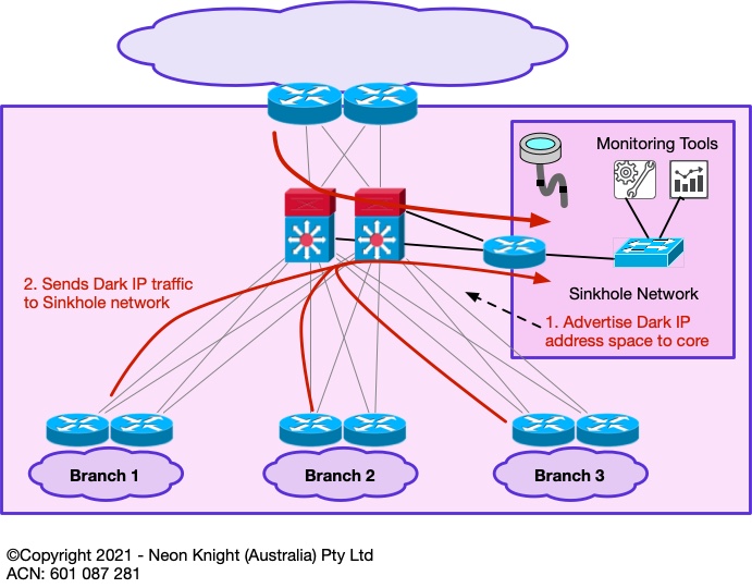
Following on from the concept of monitoring Dark Address space – a Sinkhole is a networking tool which can be used for this function.
A sinkhole is essentially an area of the network, that ‘sucks in’ traffic that has no other destination, or traffic that we wish to analyse in more detail. Sinkholes were originally developed within the Service Provider community for the purpose of monitoring illegitimate traffic or drawing in portions of DDoS attack traffic for further analysis.
Within an enterprise network, a sinkhole can be established to draw in traffic to some (small, or large) address block for monitoring purposes. The recommended deployment approach is to start with a smaller unused address block (or blocks) and monitor the resulting traffic volumes. Sinkholes are capable of drawing large traffic volumes, so a careful deployment approach is recommended. A high bandwidth link into the network core is also recommended.
Figure 1 provides an example of a Sinkhole network.
Routing to Null 0
For completeness it is worth introducing the concept of routing to Null 0, also known as Black Hole routing. Although hardware-based ACLs are fast. Null 0 routing avoids the use of the finite TCAM resources entirely. Its only limitation is the size of the routing table which is generally a non-issue in 2021.
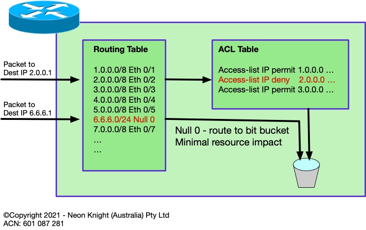
Figure 2 illustrates the concept and compares the paths taken by two packets of different destination addresses.
Black Hole Routing
The document started by discussing hardware-based ACLs. The key point of that section was to highlight that router and switch ACLs could today be used to implement security policy at very high speeds, well beyond what firewalls can provide.
Subsequent sections will progressively describe a number of Black Hole techniques. So, first it is important to introduce the concept of Black Hole routing. In the same way a simple ACL can be used to block access to one or more destination addresses, Black Hole routing can equally effectively route any prefix to ‘null 0’, which as the name implies, sends the traffic to a black hole and drops it at routing speed, generally with no performance implications.
Using the Cisco configuration syntax as an example, the following ACL:
access-list 10 permit 203.0.113.0 0.0.0.255
could be replaced with:
interface Null0
no icmp unreachables
ip route 203.0.113.0 255.255.255.0 null 0
The obvious observation from the above example is that it is limited to destination prefixes. This observation is correct at this point, however, as the discussion progresses examples of dropping based on source addresses will be discussed.
Remote Trigger Black Hole Routing
The previous section described the basic concept of Black Hole Routing. In practice, a static deployment is not a widely used technique. However, through the use of BGP, a remote trigger function can be created. This can be incredibly useful for dropping traffic to specific IP addresses at any Point-in-the-Network. In practice, it is most commonly used at the Internet perimeter. The technique is known as Remote Trigger Black Hole (RTBH).
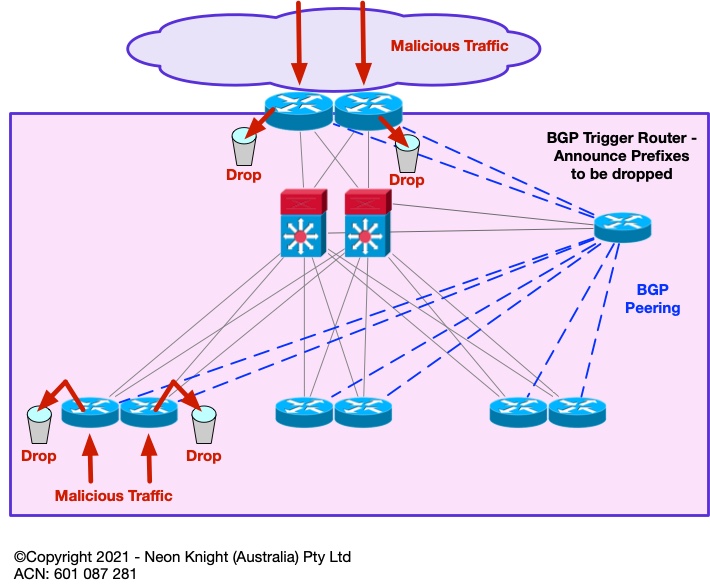
It operates as follows – BGP is used to propagate the prefixes to-be-dropped. As BGP is both highly scalable, and can peer with multiple devices, the approach scales to large numbers of prefixes and can perform the function at multiple Points-in-the-Network concurrently. Unlike most firewalls which require a slow commit process, the drop function can be performed almost instantaneously.
Such an approach can be highly architecturally valuable in very large-scale networks such as Internet Service Providers, Telcos, Mobile Network Infrastructure, etc. However, it can also be valuable in more modestly sized environments. In particular if there is an operational requirement to drop malicious traffic without delay, or incorporating such a function into an automated response. As this technique uses standard router functionality, there is little to no additional costs.
Figure 3 illustrates the high-level architecture including the BGP peers which are used from the trigger router to the drop points.
At a routing level the mechanism in Figure 4 is used to achieve the drop function. For example, lets say prefix 203.0.113.0/24 is deemed to be a malicious source. This prefix would be announced from the trigger router with a next-hop of an intermediate address. In this case the TEST NET of 192.0.2.1 is used. A locally configured static route is required on each edge router with a next-hop of NULL 0. When the edge router receives the prefix-to-be-dropped via BGP, it associates it to NULL 0 through the intermediate static route. So, finally any traffic to the Malicious source will be dropped within the routing path. This action can occur at many Points-in-the-Network simultaneously.
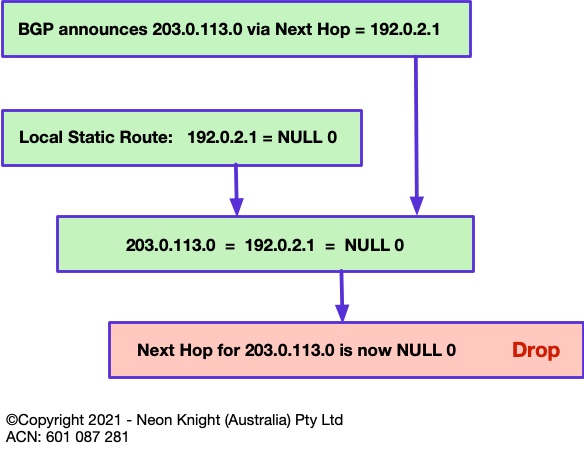
The prefix-to-be-dropped may be a public IPv46 address, or could be an internal private address. However, for internal addresses within a typical enterprise network, the location of any NAT would obviously need to be considered. Although only IPv4 is described here, the same approach can be equally used for IPv6.
At this point it has probably been noted that the technique is limited to ‘destination’ IP address only. While this in itself can be effective in blocking communication to a malicious address, it would certainly be far more useful is the technique could also black hole ‘source’ addresses. Subsequent section will describe how the technique can additionally block on source addresses.
The focus of this article is the architectural concept. In practice the deployment of RTBH does involve a little more complexity than is presented here. The References Section provide links to a sources which describe the deployment and configuration in more detail.
Unicast RPF
Unicast Reverse Path Forwarding (uRPF) provides functionality to drop illegitimate or malicious traffic arriving on interfaces from which it likely never originated. The original idea was defined in RFC 2827 with the intention to block incoming traffic on an interface if its source address was forged or spoofed.
In addition to uRPF now being a very standard router and switch feature, it is also a standard feature on any quality firewall.
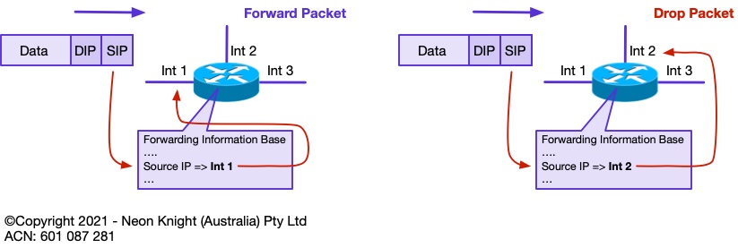
The most common mode of operation of uRPF is ‘Strict’ mode. If a packet is received on an interface, a route to that packets source address must be available via the same interface on which the packet was received. If this route does not exist, then the packet fails the Reverse Path Forwarding check and is dropped. On quality routers and switches uRPF operation typically happens with negligible performance impact. Figure 5 illustrates the concept.
Unicast RPF in ‘Loose’ mode is a relaxation of the strict mode of operation. In loose mode, the only requirement is that the source address be in the routers Forwarding Information Base (FIB). If either the route does not exist in the FIB, or has a destination IP address of NULL0, then the packet is dropped.
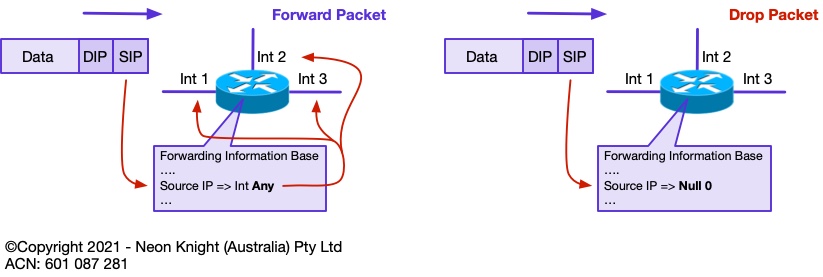
Figure 6 illustrates the concept of loose mode operation. Loose mode uRPF is the enabler of Source address based RTBH.
Source Remote Trigger Black Hole
Loose mode Unicast RPF is the mechanism which enables remote triggered black hole routing to additionally drop on source address. When Unicast RPF loose mode is configured, any ‘source’ address or addresses with a prefix corresponding to NULL 0 will also be dropped. This occurs in addition to destination addresses.
The same technique of distributing the to-be-dropped prefixes via BGP with a next hop of 192.0.2.1 is used. In the same manner as the destination address, source addresses are also routed to NULL 0 and dropped due to Loose uRPF.
BGP as a protocol is capable of carrying hundreds of thousands of prefixes. As such, this technique is highly scalable and can potentially be used to black hole very large numbers of individual (/32) source addresses, or prefixes.
SRTBH was originally developed in the early 2000s for mitigating DDoS attacks within Service Provider networks. If the individual IP addresses comprising the attack could be identified (as they often could in those days), then SRTBH could be used to drop attack traffic from those sources at the provider’s network edge or peering points. SRTBH provided an effective tool within those bounds and is still used widely in many providers today.
In an enterprise context, SRTBH is an effective tool for quickly blocking any address involved in an attack, either external or internal. The speed at which this action occurs is the key benefit. Many attacks have occurred where critical data is exfiltrated from an internal system to an attacker on the internet. Shutting down these actions quickly can be critical and may be the difference between thwarting an attack and being in the news.
Flowspec – RFC 5575 /RFC 8955
While RTBH and SRTBH are very effective tools, they can be somewhat complex to deploy and operate. Although some extensions have been created to perform functions such as rate limiting, RTBH and SRTBH are essentially ‘drop’ mechanisms.
Quality routers have for many years included rich feature sets including functionality to not only forward traffic, but to also classify, shape, rate limit, filter, or redirect packets.
RFC8955 (which now obsoletes RFC 5575) defines a general procedure to encode traffic Flow Specifications so that they can be distributed within the BGP protocol. This approach is generally known as Flowspec, or BGP Flowspec.
Flowspec is a newer approach which was primarily designed for use within Service Provider and Telco networks. It also uses BGP to propagate information about one or more actions to perform on specific traffic flows, such as malicious or attack traffic.
Although vendor support is expanding, Flowspec tends to be limited to higher-end SP focused platforms. It is important to understand its availability within the intended, or currently deployed vendor products including the specific models.
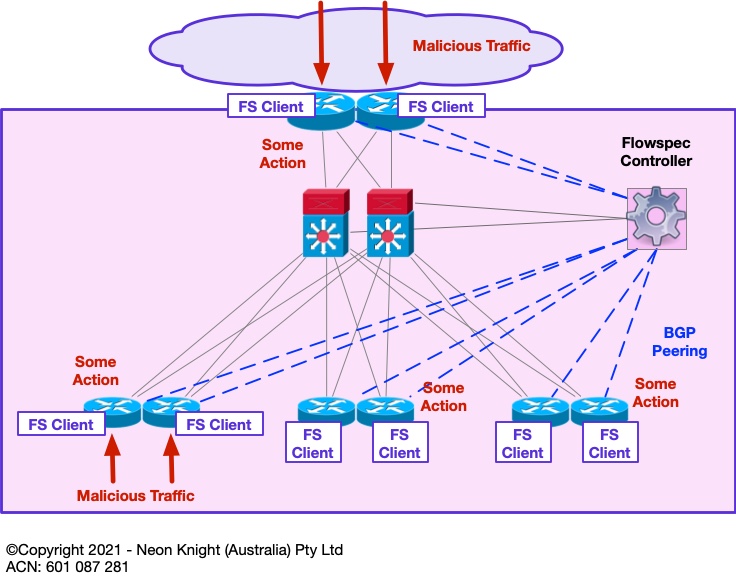
Flowspec operates using a Controller/Client architecture. A controller resides at the Head End and initiates the sending of a Traffic Description and an associated Action to multiple clients residing at various Points-in-the-Network. Figure 7provides a high-level illustration. In this example some malicious traffic enters the network at various points. The Flowspec client on the network element (i.e. router, switch, etc) can then be instructed to take some action on that traffic.
Within Flowspec traffic can be described based on L3 and L4 information, including;
- IPv46 Address
- Port (TCP, UDP)
- ICMP type and code
- TCP flag
- Packet length
- Fragmentation flags
Actions can include or be a mix of;
- Rate-limit / Drop based on a remote ACL
- DSCP remarking
- Next Hop modification for traffic diversion
- VRF leaking
- Remote Policy Based Routing: redirect packet in VRF X
- Remote Policy Based Routing: redirect packet to @IP X
Within a large enterprise, Flowspec could be used at a centralised point to block network borne malware (such as Ransomware) based on its propagation vector. In the event of a malware outbreak, time is critical and the speed of the response is often more important than perfection. Many organisations today are struggling to adequately segment their networks. Such an architectural approach allows a block action to be rapidly deployed (or pre-deployed) so that an outbreak can potentially contained to a small portion of the network.
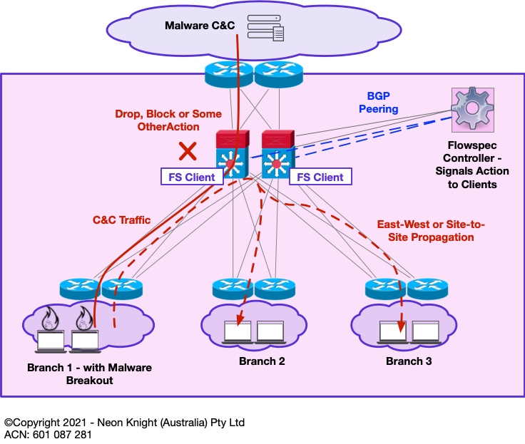
Figure 8 provides an example of a centralised Flowspec architecture. In the event that some malware event is detected through a suitable Analytics Platform[1] and its propagation vector is identified, a Flowspec controller can rapidly push some policy to block that propagation vector. In addition, associated Command-and-Control channels could also be blocked[2]. While this architecture may not save the portion of the network that contained patient zero, it may save the rest of the network from a widespread catastrophe.
What Makes BGP Flowspec Better?
- Provides the same granularity as ACLs
- Can be based on n-tuple matching
- The same automation as RTBH
- Provides a much easier method to propagate filters to all edge routers in large networks
- Can leverages BGP’s scalable architecture, best practices and policy controls
- The same filtering and best practices used for RTBH can be applied to BGP Flowspec
[1] The Awake platform from Arista and Darktrace are two examples.
[2] Blocking C&C channels may require more care/consideration with some Ransomware variants.
Private VLANs
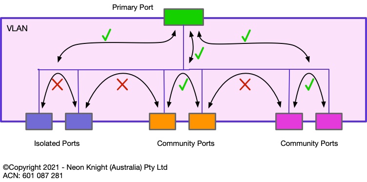
Private VLANs are a Layer 2 Switch security technique which has been in existence for over 20 years. Private VLANs work on the principal of isolating either individual devices, or groups of devices (known as communities) from other devices or groups. Private VLANs can be loosely considered a Segmentation construct. Figure 9 illustrates of the principal.
The primary port (also sometimes known as the promiscuous port) can communicate with all Isolated and Community ports. Isolated ports are not allowed to communicate with other Isolated ports or community ports. Ports within the same community can communicate with each other in the community.
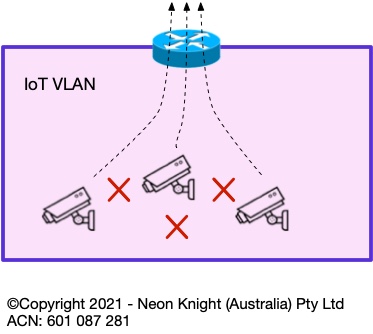
Private VLANs can be highly effective in situations where devices within a VLAN have no requirement to speak with other devices within the same VLAN, only needing to communicate upstream of the VLAN’s default gateway. For example, Figure 10 shows an example of multiple IoT devices within a VLAN. None of these devices have any requirement to communicate with each other inside the VLAN, typically only the head-end recorder. In this case, Private VLANs provide an additional form of segmentation which can prevent an attack, or malware, propagating from one device to another.
Within the wireless domain, similar techniques such as Station Isolation and Peer-to-Peer blocking can be used to prevent devices within a single SSID from communicating with each other at layer 2.
From an administrative perspective, these techniques do require to be administered by the networking teams as opposed to the security teams. Such operational demarcations exist in many organisations which sometimes make deployment more involved.
Furter Information
Remote Trigger Blackhole
https://www.cisco.com/c/dam/en_us/about/security/intelligence/blackhole.pdf
https://www.senki.org/operators-security-toolkit/remote-triggered-black-hole-rtbh-filtering/
Flowspec
https://datatracker.ietf.org/doc/html/rfc8955