Ethernet VPN (EVPN) in Zero Trust Security Architecture
Whitepaper
19 August 2025
Draft Version 1.0
Table of Contents
Some Common Firewall-Based Security Architectures 3
Fundamental Network Separation Approaches 6
MPLS Transport – A Background Perspective 6
A quick introduction to VXLAN and Ethernet VPN (EVPN) 9
EVPN Network Design and Deployment Considerations 11
Alternative Approaches utilising EVPN/VXLAN 12
Scenario 3 – Larger Scale Example – External access 14
Network Infrastructure Security 16
Enhancing Security – IPsec and VXLAN 17
Executive Summary
As a consulting company, Neon Knight has observed many Enterprise and Telco Security Architectures. This Whitepaper was prompted based on those observations and other technology trends such as the broad interest in Zero Trust based architectures.
Firewalls have become a very dominant approach in foundational Network Security Architectures. Firewalls are, and will continue to be, a necessary element of these architectures. However, Firewalls and Next-Generation Firewalls are expensive and, in most cases, require complex security policy. Maintaining this complex security policy is operationally expensive.
Isolation or separation is a fundamental concept in Network Security Architecture, often known as Security Zones. It is easily achievable within a single site using constructs such as VLANs (layer-2) and Virtual Routing instances (layer-3).
The ability to stretch those Zones across an Enterprise is more difficult, particularly as many enterprises often rely on IP-based Telco services for wide-area or metropolitan-area interconnection. Achieving multiple, enterprise-wide Zones has typically required a private, MPLS core network deployment or the use of complex overlaid tunnels. Very few enterprises have MPLS core networks and very few network teams wish to manage the complexity of tunnel overlays.
Hence many enterprise architectures have utilised internal firewalls, and the configuration of (often) complex security policy (i.e. rules) to isolate zones from each other. This approach may be functional, but when it grows beyond a small scale, it can become exponentially more complex, costly and error prone.
This Whitepaper presents some alternate security architectures utilising more recent Ethernet VPN (EVPN) and VXLAN technology. This functionality provides a means of deploying multiple, enterprise-wide, isolated L-2 and L-3 network overlays.
This whitepaper is NOT suggesting that EVPN/VXLAN is a silver bullet. However, it is a very valuable construct which can greatly assist in designing, deploying and scaling Zero Trust based architectures. Many security engineers may not be aware of its existence or how it could be used.
The purpose of this document is not to repeat the fundamental network-level EVPN/VXLAN theory, but to focus on how EVPN technology can be used to potentially strengthen and simplify network security architecture.
Some Common Firewall-Based Security Architectures
Let’s look at two very common, Firewall-based architectures.
Scenario 1
The first is common in large campus networks. Often multiple isolated Layer-3 networks (or VRFs) are interconnected via a central or core Firewall which provides both the centralised routing and the security policy. As noted earlier, these isolated networks can be referred to as Zones. Typically, all devices within a zone communicate freely. However, firewall policy (i.e. rules) are required to explicitly permit traffic between the various zones. By default, no traffic will be permitted unless some matching rule is configured.
It is common to observe each building being a single Layer-3 domain and a single security zone. Unless specific subnets, i.e. say the security cameras, are explicitly trunked to a firewall as their own zone, then often every device in that zone can reach every other device. The security granularity of this approach is typically very limited.
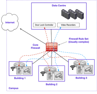
Figure 1 – Campus Network Example
Figure 1 illustrates a simplified large campus example. In these environments, it is common that much of the traffic will need to be routed to and from a data centre. Let’s consider a common scenario of the centralised door lock controller and video head-end are located in the DC. Across the numerous buildings are many door locks and security cameras. In a large environment, there could easily be many hundreds or more of each.
While there will always be variations, typically such an architecture requires high-end Core or DC-Class Firewalls to meet the throughput requirements. It is also common to observe undersized firewalls impacting overall throughput and hence user experience.
Given the complexity of the traffic traversing the core firewalls, many objects and security policy entries are typically required. This goes beyond just the initial configuration. Constant adds, moves, changes and various forms of network flux require a considerable amount operational activity and cost.
Assuming typically broad security zones, there is an obvious security risk of often inherently insecure IoT devices, being used as an attack foothold and then a stepping stone for lateral movement in a multi-stage security breach.
Scenario 2
A second and related example considers an Enterprise-wide scenario. Many enterprises have deployed a Firewall Overlay, sometimes known as a Hybrid Mesh. The purpose of which is to firstly isolate/segment riskier assets from the main corporate network. Then in many cases the architecture allows restricted communication between related security zones at different sites, with traffic simply traversing the main corporate network. Firewall rules are used to control this communication.
As examples, the following are real life examples of systems that require isolation and segmentation.
- Building Management systems
- Healthcare systems, MRI, CT scanners, etc (which are often outsourced to an equipment vendor requiring remote access)
- IoT equipment with obsolete/unmaintained OS (i.e., Windows XP, Windows 7, etc)
- Scientific or research equipment
- EFTPOS machines and POS networks
- Video cameras and other IoT devices
- Industrial Control Systems, SCADA, etc
- Networks with sensitive security implications.
Figure 2 provides a simplified example of just two sites and two isolated networks in each site.
- Site 1 has Isolated Zones Red and Blue.
- Site 2 has Isolated Zones Red and Blue.
- Assume Site 1 Red and Site 2 Red need to communicate.
- Likewise, Site 1 Blue and Site 2 Blue need to communicate.
- That communication is permitted through respective firewall configuration
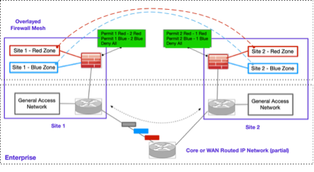
Figure 2 – Multiple sites with a Firewall Overlay (simplified)
While this approach achieves the architectural goals, it has several issues.
- it is complex. The complexity of the required security policy can grow exponentially as the number of sites and zones grow. This can quickly become a scaling and operational cost problem.
- Complex approaches are very prone to errors.
- The networks are not truly isolated. Traffic between zones on different sites still traverses the main corporate network.
- Any firewall platform is expensive. Multiplying the platform numbers by many sites can quickly become a very expensive architecture. With that said, a firewall platform per site may be required in any case, but additional interfaces and capacity can still be a factor.
While this example considers only two sites, with two zones per site, in large enterprise networks, these numbers may be significantly higher (i.e. hundreds, thousands).
Fundamental Network Separation Approaches
VLANs and Virtual Routers
Quickly stepping back to the basics. In modern networks, typically the Virtual LAN (VLAN) is the most fundamental Layer-2 construct. 802.1Q is the mechanism that allows multiple VLANs to be trunked on a single physical link. Sub-interfaces reside on a router or firewall to provide a Layer-3 gateway for the respective VLANs.
Virtual Routing and Forwarding instances (VRFs) provide an isolation construct at Layer-3. Modern routers and switches typically provide support for multiple VRFs at a hardware level. This typically allows multiple VRFs to be configured on an individual router or switch.
VRFs are a construct local to the switch or router. An additional mechanism is required to maintain this isolation when routing traffic between VRFs on different routers or switches in the network. If a physical path is available such as a direct Ethernet cable or dark fibre, an 802.1Q trunk is an easy option.
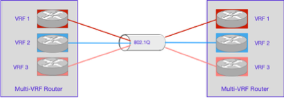
Figure 3 – Multi-VRF Router and 802.1Q interconnect
However, if only a non-802.1Q capable point-to-point Ethernet service, or IP-based Layer-3 link, then solutions become more involved (more on that soon).
MPLS Transport – A Background Perspective
In an enterprise-wide, multi-VRF environment Multiprotocol Label Switching (MPLS) can be used to direct traffic by assigning unique labels to packets based on their Virtual Routing and Forwarding (VRF) instance. These labels, added at the ingress Provider Edge (PE) router, determine the forwarding path through an MPLS enabled core network. Each VRF maintains a separate routing table, ensuring traffic isolation between VRFs. The labels are swapped at Label Switch Routers (LSR) in the path until the packet reaches its egress PE, where the label is removed, and the packet is forwarded to the correct destination network based on the VRF configuration.
While it is common for Telcos to utilise MPLS as a foundation of their infrastructure, it is far less common for Enterprise networks (large or small) to have deployed private MPLS infrastructure. Private MPLS infrastructure can be used to provide a valuable security construct. However, such infrastructure is usually very costly as it often requires Telco class products and licensing, as well as more specialised skills and staffing to deploy and operate.
For these reasons, very few Enterprise networks have deployed MPLS. This limits their ability to easily and scalably support their own overlaid Layer-2 or Layer-3 networks.
Other Approaches
To complement the discussion, MPLS-based infrastructure is not the only option to link disparate VRFs within an enterprise network. Other approaches are available but involve more complexity.
- Dedicated 802.1Q trunking between VRFs is one previously noted option. However, 802.1Q is usually not available over the today’s commonly utilised wide area Telco services. Even where the Telco service supports it, such as dark-fibre, substantial configuration is required to deploy it enterprise-wide. i.e. it requires configuration and mapping on every link of a potentially large or growing network.
- Overlaid Tunnels such as GRE or IPsec are an option, but typically also require substantial manual configuration and don’t easily scale beyond small numbers of sites and VRFs.
- Vendor-specific approaches such as Cisco’s Security Group Tags (SGTs) can provide this functionality but are typically thinly deployed.
- SD-WAN technology from multiple vendors can provide isolated circuits over the wide-area. Again, this can be complex in a larger environment with many sites and many VRFs.
So, design options certainly exist. However, all have design considerations, constraints and limitations with scaling and configuration complexity being significant factors.
A Zero Trust Context
Zero Trust is a comprehensive security framework that assumes no inherent trust in any user, device, or network. While Zero Trust is a large and complex domain. Within the context of this Whitepaper, it is important to understand two fundamental Zero Trust Architecture paradigms.
- Isolation, Segmentation and Micro-segmentation – refers to dividing the network into isolated, granular zones typically containing devices of like security affinity. Each segment provides a distinct security boundary. That boundary controls access which in turn can limit any lateral movement of attackers.
- Moving the Protect Surface Closer to Data Assets – Zero Trust emphasizes applying security controls as close as possible to sensitive data assets. This is an evolution of the traditional perimeter-based security architecture still used by most Enterprises.
For many enterprises achieving these goals has been a difficult process. Some of the challenges have included;
- Complexity of Network Design – Any large Layer-2 domains have historically required the use of large and complex spanning tree deployments.
- Limitations of a single, enterprise-wide, routing domain – These were originally designed for wide internal reachability, not security separation.
- Scalability of Segmentation Policies – As enterprises grow, the number of diverse workloads, users, and devices increases, potentially requiring large numbers of micro-segments. Managing granular policies across many segments becomes complex, resource-intensive, especially when policies must be dynamically updated to address new threats and/or changing business needs.
- Policy Consistency Across Distributed Environments – As the number of protect surfaces grows, so does the complexity of maintaining the policies in a consistent manner.
- Preventing complex functionality sprawl – An ability to consolidate geographically diverse, but functionally similar devices into a single security zone.
The next section will introduce Ethernet VPN and VXLAN. While this is not specifically a security function, it does provide an underlying networking construct which can provide new deployment options.
A quick introduction to VXLAN and Ethernet VPN (EVPN)
Positioning VXLAN and EVPN
VXLAN (Virtual eXtensible Local Area Network) / EVPN (Ethernet VPN) is a more recent networking technology which now is widely deployed within Datacentre infrastructure, including virtually all hyper-scale networks. It is based on a Leaf-Spine architecture which provides significant benefits over previous Spanning-Tree based designs.
At the most fundamental level, VXLAN EVPN allows a standards-based, highly scalable mechanism to deploy network-wide, isolated Layer-2 or Layer-3 overlays on a routed IP network. These are known as virtual networks. These can be deployed without the need for an underlying MPLS infrastructure or other complex alternatives.
The EVPN construct provide significant additional flexibility in foundational network design. As a result, enterprise-wide overlays can confidently be deployed at scale. Such a capability should be seen as a game-changer in network security design.
VXLAN Background
Virtual eXtensible Local Area Network (VXLAN) was originally defined in RFC 7348 as an overlay technology to provide Layer-2 and Layer-3 connectivity services over a generic IP network.
VXLAN provides this functionality in a highly scalable manner, with high performance and predictable failure recovery. VXLAN achieves this by tunnelling Layer-2/Layer-3 frames inside of IP packets. VXLAN requires only IP reachability between the VXLAN capable edge devices, provided by an underlying IP network.
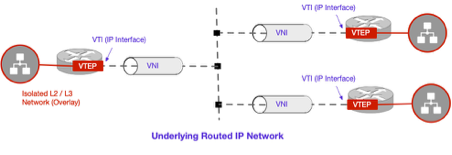
Figure 4 – VXLAN EVPN High-Level Concept
Figure 4 provides a high-level conceptual illustration of the key VXLAN components.
- VTEP – Virtual Tunnel Endpoint: The hardware or software element at the edge of the network responsible for instantiating the VXLAN tunnel/tunnels and performing VXLAN encapsulation and decapsulation
- VNI – Virtual Network Instance: A logical network instance providing Layer-2 or Layer-3 services and defining a Layer-2 broadcast domain
- VNID – Virtual Network Identifier: A 24-bit segment ID that allows the addressing of up to 16 million logical networks to be present in the same administrative domain
- VN – Virtual Network: The general term for the Virtual Network Instance defined above.
- VTI – Virtual Tunnel Identifier – An IP interface used as the Source IP address for the encapsulated VXLAN traffic with the IP addresses residing in the underlay network.
The VXLAN Tunnel Endpoint Function can be performed by a hardware device or by a software entity such as a hypervisor. The main advantage of using a hardware-based tunnel endpoint is the enhanced performance offered through the capabilities of the switch ASICs.
For reference and further clarity, Figure 5 provides an illustration of the VXLAN packet format showing how original frames are carried as a payload.
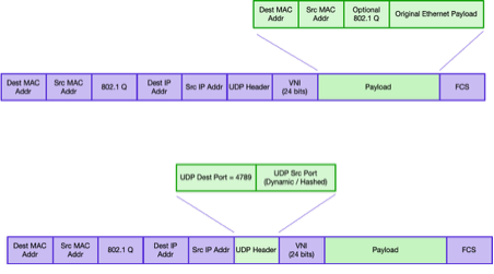
Figure 5 – VXLAN Packet Format
EVPN – The Control Plane
It is important to understand that VXLAN without its partner EVPN, leverages flood and learn behaviour. This is essentially how a traditional switch (or Bridge) behaves. If it does not know the destination MAC address, it floods the frame throughout the switch domain (i.e. broadcast domain) and learns the MAC addresses network location when the response comes back.
EVPN provides the control plane for VXLAN and provides an efficient method for route (or MAC) learning and distribution in the VXLAN overlay network. The routing information includes Layer-2 MAC routes, Layer-3 Host IP routes, and Layer-3 subnet IP routes. The EVPN control plane also introduces multi-tenancy support (i.e., overlapping address space) to the VXLAN overlay network, as well as a VTEP peer discovery, security, and an authentication mechanism.
EVPN uses MP-BGP (Multi-Protocol Border Gateway Protocol) as the routing protocol to distribute reachability information for the VXLAN overlay network This includes endpoint MAC addresses, endpoint IP addresses, and subnet reachability information. EVPN is an additional MP-BGP Address Family (AF) leveraging similar constructs as the VPNv4 address family traditionally deployed in MPLS VPN architectures.
Why this matters – The EVPN control plane is critical because it enables efficient, scalable, and flexible Layer-2 and Layer-3 connectivity. Using BGP, it dynamically distributes MAC and IP address information across sites in a highly scalable manner.
EVPN Network Design and Deployment Considerations
It is important to understand that EVPN/VXLAN does require network design and deployment. That does require both the network-level functionality and human expertise. As the focus of this Whitepaper is on Security, consider the underlying complexity abstracted away. In a practical deployment, the networking team would need to be utilised.
Alternative Approaches utilising EVPN/VXLAN
Scenario 1
Having originally presented some common, but simplified firewall-based design scenarios, we will now look at alternative approaches utilising EVPN.
Let’s redesign the original campus example utilising EVPN/VXLAN as illustrated in Figure 6.
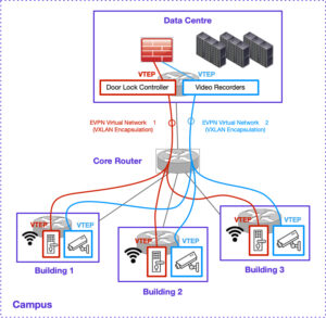
Figure 6 – Campus VXLAN / EVPN Overlay
The primary advantage of this approach is the previously utilised core Firewall is replaced with a more traditional core router. The Firewall can be moved to the edge. Previously a very high-performance core Firewall would have been required to provide the necessary packet forwarding rates for the core of such a network. Such devices were typically extremely expensive in comparison to core router platforms and often they were undersized (due to cost) and the whole network performance suffered as a result.
With the use of EVPN in the above scenario, two campus-wide, Virtual Networks (VNs) are deployed. The door locks and video cameras are now deployed on their own respective VNs, isolating the (often insecure) endpoints from other devices on the network. No complex (or at least greatly simplified) security policy is required and the original device addressing can be retained making migration straightforward.
Consider that in the original design back in Figure 1, all security cameras and door locks would potentially have been reachable by any endpoint in the whole VRF[1]. Devices like security cameras and door locks are often IoT class devices with poor default security postures. This makes them easy targets for attackers. Without these devices being isolated into their own network, they are easy targets which risk them becoming a foothold and stepping stone for attack progression (i.e. Lateral movement). Many high-profile and damaging attacks have followed this trajectory.
Scenario 2
Let’s redesign the second Enterprise example, originally illustrated in Figure 2 utilising EVPN/VXLAN. Figure 7 illustrates the new approach. In a conceptually similar manner to Scenario 1, the hybrid mesh firewalls have been removed[2].
Only two sites are included in this example for simplicity, however in practice there could be hundreds (or thousands) of sites involved and many hundreds or more isolated networks if required.
The key point is that this approach is very scalable.
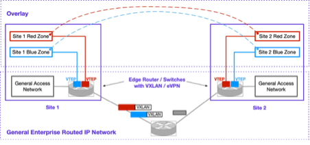
Figure 7 – Multi-site Enterprise
Rather than utilising dedicated hybrid-mesh firewalls at each site, each isolated network is simply connected to its own VN. At a network level, the red and blue zone are now mapped onto VNs which utilise VXLAN/EVPN. The VXLAN-encapsulated traffic is simply routed over the standard IP core network with regular non-VXLAN traffic.
It is worth noting that traffic within a VN traverses the IP Network encapsulated in a VXLAN packet. This traffic is not encrypted as would happen with IPsec, however it does provide some level of separation from the standard IPv4 core network traffic.
Scenario 3 – Larger Scale Example – External access
Let’s consider a third example. The first two scenarios were intended to simply illustrate some alternate design options. In this example we will consider a higher scale use case.
External Business Partner (EBP) access is a common design scenario observed across many organisations, in particular where an external entity manages systems inside the organisation. There have been numerous high-profile breaches where external business partner access has provided an entry vector and permitted a foothold to be established. Subsequently the attack progressed further through lateral movement.
Two notable examples.
- Building management systems (BMS) such as Heating, Ventilation, Air Conditioning (HVAC). These are commonly managed by an external entity who requires remote access to these systems. Often these systems have poor default security posture. Often the external entity has a questionable security posture.
- In healthcare, often specialised medical systems like MRI and CT, which often operate 24×7 due to the high equipment cost. Such systems are commonly supported by the equipment vendor with tight Service Level Agreements. Remote access is an essential requirement.
Let’s consider one design approach, although many variations of the same fundamental theme are possible.
In this scenario, let’s assume an Enterprise has two external business partners (hypothetically). One who provides support services for some medical infrastructure. A second who provides support services to their Building Management Systems (a very common scenario in practice).
To isolate these systems from the main enterprise network, two VNs are overlaid on top of the enterprise network using EVPN/VXLAN. Via an IPsec Gateway, IPsec Remote Access is used by the external business partners to access their respective VNs and hence the equipment inside them. Figure 8 provides a conceptual illustration.
A AAA (Authentication, Authorization, Accounting) system such as RADIUS provides the Identity function. RADIUS Vendor Specific Attributes (VSA) can be used in conjunction with the IPsec Gateway to associate the business partners’ Identity of the IPsec session to the respective VN. A RADIUS Server utilising VSAs[3] is not the only solution but certainly is a commonly supported approach. Given the VNs are inherently isolated, the EBP can’t access anything outside the infrastructure within its VN.
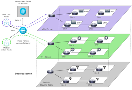
Figure 8 – Enterprise Network with Remote Access to VNs
While only two VNs were illustrated in this example, in practice far larger scale is easily supported. This architecture could support many hundreds of EVPN/VXLAN VN overlays if required.
Note: From a practical perspective, the author has previously deployed a very similar security architecture within a Mobile Network Operator (MNO) infrastructure design. While this design and deployment pre-dated EVPN/VXLAN, it did use MPLS based VRFs (with per-VRF IPsec) and the security principals were near identical. In this case, several separate organisations required remote access into the core operational systems. These systems were functionally separated through the use on individual VRFs.
Network Infrastructure Security
As this Whitepaper has proposed the use of a network-based construct as an alternative to firewall based approaches, it must be strongly noted that the security of the network infrastructure is vitally important. If network devices are compromised, or accessed by malicious parties, then a whole range of severe alterations are possible. Regardless of the use of EVPN/VXLAN, it is crucial that the security posture of all network infrastructure is robust. All vendors have hardening guides which should be followed rigorously.
Enhancing Security – IPsec and VXLAN
IPsec can be integrated with VXLAN to enhance security by encrypting the payload of VXLAN-encapsulated traffic, ensuring confidentiality and integrity across untrusted (or semi-trusted) Layer-3 networks. As outlined in RFC 7348, which defines VXLAN, IPsec can be applied to secure VXLAN traffic, typically using the Encapsulating Security Payload (ESP) protocol (RFC 4303) in transport mode to encrypt the VXLAN payload while preserving the outer IP header for routing. This combination enables secure Layer-2 connectivity over wide-area networks, protecting against eavesdropping and tampering. Additionally, drafts like “draft-sajassi-bess-secure-evpn” explore security mechanisms for VXLAN in EVPN contexts, reinforcing the use of IPsec to safeguard virtualized network traffic.
Conclusion
Many enterprises have struggled with the task of segmenting their networks to achieve an improved security posture. The adoption of Ethernet VPN (EVPN) and VXLAN can offer substantial benefits when designing and scaling Zero Trust security architectures. These include reduced complexity and cost, as well as additional technical capability.
The paper showed two increasingly common firewall use cases which could potentially be implemented using an alternate EVPN/VXLAN approach.
Neon Knight Consulting Pty Ltd encourages security and network engineers to explore EVPN/VXLAN’s potential. We are available for consulting engagements to help customers deploy and strengthen network security.
_
[1] Unless either network-level ACLs were deployed, or those specific VLANs were trunked to a dedicated interface of the core firewall.
[2] In practice firewalls still would likely still exist somewhere for Internet connectivity, etc, but would likely be pushed to the edge of the VN. In any case, this level of design is going beyond the conceptual intent of this whitepaper.
[3] Example VSA syntax, sent from RADIUS server to IPsec GW: cisco-av-pair = “ip:vrf-id=BMS_VRF”