©Copyright 2015 – Neon Knight (Australia) Pty Ltd
ACN: 601 087 281
Introduction and Positioning
This document is one of a series of White Papers on the subject of Network Security Architecture and Design. The Document was written in 2015 with the aim of providing an up-to-date coverage of the topic.
In recent years, huge changes have occurred to both the global security landscape and also to way that businesses run their IT operations. As such, there are many aspects of Network Security Architecture which need to be updated and expanded to address these changes and trends. That is the key focus of this series of White Papers.
The purpose of this first White Paper is to explain the “fundamentals” of Network Security Architecture and Design. It will not be an exhaustive coverage of all aspects of the field, but hopefully provide a foundation and hit the key points prior to moving onto the newer considerations.
The field of Network Security Architecture has now been around for around 20 years or more. While many changes have occurred, there are many aspects of the field which are relatively static and will most likely remain static going forward. Additionally many lessons have been learned over that time, which should not be ignored.
Based on the significantly changed security and threat landscape, a second White Paper will discus those changes and their effect on the fundamental requirements of a Network Security Architecture.
Subsequent documents will cover various specific areas in more depth, including approaches to operationalizing security, including the deployment of Cyber Kill Chains(1).
(1) 1 CYBER KILL CHAIN is a registered trademark of Lockheed Martin Corporation.
Background
As a consultant, I have worked with a large number of clients across the globe in many different verticals. I have observed some very mature security architectures and operations. Unfortunately, I have also seen many fair to mediocre ones. I believe anyone who has ever heard me speak publicly about either security or network architectures, would have heard me emphasise the importance of a strong fundamental architecture. My analogy is that of a multi-story building – if you don’t have strong foundations, then the integrity of the structure is always going to be weak. Sure you can try to retrofit things to improve the situation, but it is usually a loosing proposition.
I am not trying suggest that a fundamentally strong network security architecture will solve all security issues, there is a lot more involved, like mature processes and procedures. But like a multi-story building, if you have a strong foundation and a good solid design, then you will be in good shape to move forward with confidence. That’s what this is all about, getting the basic approach right and having a strong foundation. I first saw the value of solid architectural approaches over a decade ago when the likes of SQL Slammer and Blaster first hit the internet. I observed that the organisations with fundamentally strong underlying security architectures, were in most cases far less impacted than those without. I have carried this philosophy forward since that time.
The fundamentals of Network Security Architectures
A good analogy for looking at the fundamentals of security architecture is to draw a comparison with medieval castles. Many of these castles were designed with a great deal of consideration for protecting against the attacks of the period. When many people draw a comparison of security architecture to a castle they think of the “Castle-Moat” design, with the network security equivalent being an Internet perimeter firewall with an outside and an inside. The bad stuff is on the outside and only the good stuff gets through to the inside…right? Real castle designs were a lot more than a perimeter castle wall and a moat.
Lets have a look at Harlech Castle in Wales, built in 1283.

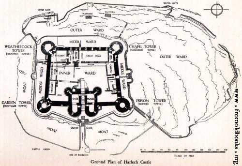
Certainly the castle has a perimeter wall and a moat, but if we examine the internal structure of the castle, then you quickly see it is constructed with a number of compartments, or wards and chambers. Compartmentalisation is one of the most important concepts in network security design. In the event of an attack successfully penetrating the perimeter, a compartmentalised structure provides the ability to restrict the spread of the attack. An example of a compartment within a network security context is a Demilaterised Zone or DMZ. These zone were traditionally used as part of a classic perimeter architecture to locate servers such as a DNS, mail relay server, and other servers which were interacting with untrusted sources out on the big bad Internet. The rationale is that in the event that one of these servers was compromised, the attack could not easily spread to the interior of the network.
Even though this design has been a classic approach for well over 15 years, I still today see organisations who don’t follow this approach. Certainly there are situations where valid reason exist, particularly in smaller environments, with very tight or limited budgets. In many of these environments, a single server is used for many functions. It may be the DNS, and the mail server and the file share for the office. In this case, its a tougher problem, and you move into the realm of a sub-optimal architecture, and the need to use compensating controls. That’s situation we can discuss in more detail later in the document. To circle back to the original point, a DMZ based approach is certainly a very valuable part of a strong security architecture.
Some further observations. Harlech Castle is built with multiple exterior walls, with the security architecture equivalent being “Multiple Layers of Defence” or the less precise term “Defence in Depth”.
There are strong points, “Towers” or “Keeps” on the perimeter walls. These served as high points providing both visibility, which we will discuss in depth, and points for archers to fire from. This architecture provides “Overlapping Fields of Fire” where defensive fire can be launched at a target from more than one point making it harder fro an attacker to shield the attack.
We can also see a drawbridge over the moat, serving as one of several “Chokepoints”, forcing traffic through specific paths where it can be properly analysed and inspected. I’ll take a bet there would also be secret escape tunnel as a “Last Resort” in the event that all else failed.
Coming back to the internal structure now. We can see the internal structure of wards and chambers. While it limits the scope of an internal attack, it also suggests that the original castle architects understood something about limiting internal trust relationships. Like Harlech castle, the use of an internally compartmentalised architecture is one of the most key network security architecture concepts.
Multiple Layers of Security
As noted above, Multiple Layers of Security is also known as Defence In Depth, or a Layered Defence Model.
The key concept behind multiple layers of security is that fact that any layer has the potential to be compromised, or to fail. While we hope that this possibility never occurs, it is essential to plan for a compromise or failure scenario in any of the deployed security controls. Having another layer which can provide protection should a layer fail, is the key principal.
What it is – In the event that a security control should fail, then there is another control which can perform the same or a similar function. An analogy is seat belts and air bags in cars, or in the castle context, both a wall and moat.
What it isn’t – This is not to say that we should just duplicate the same function in a serial manner. This is not multiple layers of security, it is a duplication of the same function. This approach has the same vulnerabilities or weaknesses as the original control. Such an approach provides little or no benefit as an attacker will usually be able to utilise the same attack technique to compromise or bypass that control.
I have seen several situations where two perimeter firewalls, from different vendors, with virtually the same security policy on each have been deployed, then claimed to have deployed a multi-layered approach. This approach is not multiple layers of security. It is essentially just duplicating the same function. In fact it often just adds administrative overhead and complexity for no net gain.
New Technology
Given that Information Security is a fast changing field, the area of new technology should be understood. If we go back to the castle analogy, we have seen that great consideration was given to defending against the attacks of the day. But how would the architecture have fared if a new attack type like a cannon and Gun Powder was to used? At this point, the existing security controls become ineffective against the new attack. It is highly likely that a new technology will be required to adequately defend against the attack.
While a subsequent White Paper will discuss the recent changes in a lot of depth, at this point it is worth saying that the threat landscape in 2015 has moved beyond many of the traditional security controls. With that said, the focus of this White Paper is to present the fundamentals prior to moving onto the changes and newer approaches which are required.
Fundamental Principals of Network Security Design
Many security frameworks have been developed over the years. However, most of these have apply to security policy, or threat and risk models. In terms of a framework to view a network security architecture and the fundamental functions it should provide, the classifications below are the best framework I have seen. The model originated within Cisco Systems in the middle of the last decade (Apx 2005 timeframe). The (slightly updated for 2015) six fundamental functions are:
- Isolation, Separation, Comartmentalisation
- Policy Enforcement
- Identity and Trust
- Instrumentation and Visibility
- Correlation
- Resilience
Following is a somewhat formal description of each of the six functions. Later parts of the paper will elaborate on the various functions, or make reference to them.
Please note: Not all security technologies will fit cleanly into a single function. Many devices or technologies perform multiple functionss and as such have multiple applicability.
Isolation, Separation, Comartmentalisation
The concepts of Isolation and Separation ensure that the effects of a disturbance, or an incident, within one part of a system, can be limited to just that part of the overall system. Through the use of isolation, disturbances or incidents within one part of the overall system can have minimal impact on other users, services, or sub-systems.
This principal provides the ability to isolate areas of a network (or system) into security zones so as to control (or prevent) access between network areas or parts of the system and hence limit the scope of exploits.
The concept of Compartmentalisation is an extension of this concept where an overall system is designed into multiple compartments. Should one compartment be breached, then that breach can be contained to a single compartment.
In a network security context, examples of Isolation constructs include VLANs, Virtual Routers, tunneling techniques, and Security Zones.
Policy Enforcement
Policy Enforcement provides the ability to enforce allowed behaviour between connected systems, users, applications, IP networks, subnets, or endpoints.
In a network security context, examples of Policy Enforcement include Access Control Lists (ACLs), firewall rules, application control, and file blocking policies.
Policy enforcement may either be static, where a control is applied on a permanent basis or dynamic, where a control is applied to specifically mitigate some discrete event or security incident.
Identity and Trust
The concept of Identity and Trust defines the ability of a system to identify entities accessing a given resource and determine a trust level or a state of trust. The Identity and subsequently the trust level may be established through the inspection of credentials or though other means.
Examples of Identity and Trust mechanisms include username and password credentials, digital certificates, multi-factor authentication, trusted IP addresses or ranges. It can also include functions like 802.1x Authentication, Network Access Control (NAC) and other end-point posture assessment facilities.
Instrumentation and Visibility
Visibility is the fundamental capability to monitor the behaviour and usage of the network including its resources, connected systems, users, applications, IP traffic, and any directly detected security events.
Correlation
A correlation function provides the interpretation and dissemination, analysis and classification of instrumentation and visibility data into meaningful operational information via the contextualisation of seemingly unrelated events, changes or traffic patterns. Event correlation is critical from a security operations perspective as it can provide the foundation to detect and respond to an incident.
Resilience
Resilience provides the ability of an architecture to withstand, adjust to and/or recover from adverse, uncontrolled, or unexpected circumstances. Resilience considerations include redundancy, high-availability device pairs or clusters, and adequate performance profiles.
Cost and Budget Constraints
This is an area on which I will elaborate further throughout the document. It is essential to consider the cost of all security elements within a Security Architecture.
It would be nice to live in a world where cost was not a design consideration. The reality is that cost is a very significant consideration in any design process. Cost needs to be considered as both ‘capital’ and ‘operational’ perspectives.
The level of security and the associated cost must be commensurate with the value of the asset that is being protected. Obviously a bank is going to have a far higher security budget than would a spare parts shop. Each have very different requirements and risk profiles.
Using a low level of security investment to protect a low value asset is not necessarily a bad thing. But in doing so you need to be very sure you understand the value of the asset and who may have an interest in it. Events over the last few years have demonstrated that some non-obvious targets were of great interest as cyber-targets.
The end goal is to use the available budget to achieve the highest possible security posture. Unfortunately today I see very large amounts of budget being allocated to technologies which are becoming less and less effective. This will be an area I will discuss in a later White Paper.
Complexity Constraints
Complexity is a significant design consideration in security architectures. It is a topic which I will discuss in more detail in later parts of this White Paper or subsequent ones. In any security design, some level of complexity is both inevitable and necessary. However like everything in a design, it is a trade off. If a design aims to minimise complexity it may possibly not sufficiently achieve its intended function. However, if a design or system becomes too complex, the system will likely be excessively costly to both implement and operate. On this basis, the complexity impact should considered carefully when making design decisions. The goal should be to achieve a system design which achieves its intended goal, with the minimum level of complexity.
Instrumentation and Visibility
I previously touched on the concept of ‘Visibility’. Security Visibility is one of the most important capabilities within any security architecture. It is the ability to see what is occurring on your network. I have seen many network security architectures which have simply had no level of visibility into the activity which was going on. In some cases significant levels of compromise have existed on these networks, some were clearly in place for extended periods, and the operations staff had absolutely no idea!
There are many forms of security visibility, some are simple and easy, others provide extensive capability. Visibility is essentially based on “Instrumentation”, and in this day and age is often an essential foundation of security analytics tools.
A key architectural consideration for visibility is that it needs to be pervasive throughout whole network infrastructure. It is not sufficient to just run it at the perimeter, and ignore the internal network.
Logging
Logging is the most fundamental level of instrumentation. Firewalls, IPS, Routers, Switches, Servers, Desktop systems, Business applications, Databases, AV, VPNs, and Access Control Systems all produce logs. While logs are a fundamental source of instrumentation, logs are also a vehicle for user accountability.
Generally log files are not in the most user friendly format, but assuming a sufficient logging level is enabled, they can provide a lot of information. Logging can be used to detect many different types of malicious events. There are many tools, some commercial, some open source, which can analyse logs to extract key information and detect potentially malicious events.
Firewall Logs
One of the most fundamental functions of a firewall is high-speed connection logging. For traffic transiting the firewall, connection logging provides a means to see exactly who connected to who and over which ports, etc. For example, a compromised device within the network may be connecting to a known Botnet Command and Control (C&C) server outside of normal office hours. Or, a device may be sending excessive amounts of mail, indicating it may be a Bot’ed host serving Spam. Devices doing ping sweeps or port scans would indicate an internal device trying to progress an internal attack. Logging can be used to detect all these types of malicious events and many more.
For just about every Firewall vendors device, logging has performance limitations. So it may not be feasible to log every connection event. If you are operating at 10 Gbit/sec speeds, the amount of log messages can easily exceed the amount of traffic which can be pushed through a SATA channel and onto a disk. So while log tuning is often a necessary activity, it is still a very valuable fundamental visibility element.
Netflow
Techniques such as Cisco’s Netflow or Junipers SFlow can be used to gain extensive visibility into the traffic which traverses a network device. Typically this means a router or a Layer-3 switch, although a number of firewalls provide this capability as well. A flow is defined as a uni-directional traffic stream which includes source and destination IP address, protocol (i.e.TCP, UDP, etc) and source and destination ports. Two forms of Netflow exist, Sampled or Full-flow. Sampled Netflow is typically used for application visibility and capacity planning. Full flow Netflow provides a full record of every flow event and is suitable for use as a security tool, especially for network level forensics.
The use of Netflow can be a very cheap and effective way of gaining a rich insight into the traffic on a network. In many cases, it can be deployed by simply enabling it and establishing a collector on an old server or a VM, running Linux. If used in conjunction with a good visibility tool, there is a lot of information which can be gained from Netflow data. If your organisation is one that has no, or limited visibility, then this is the place to start.
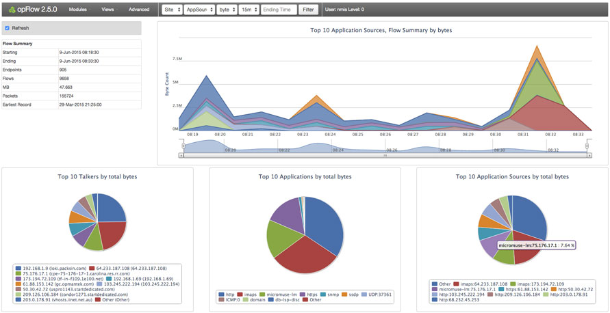
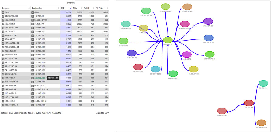
Netflow is typically used in conjunction with an external visibility tool which can consume and present the underlying raw data in a visual form. Such system can provide extensive capability. Examples of these systems include some vendors SIEMs, Cisco’s Netflow Collector and Analyzer, Solar Winds Netflow Analyser, Opmantek’s Open Flow, the open source package NFsen. Netflow can be used in its basic form or it can become the foundation of an extensive analytics package with tools from Vendors such as Intel Security, Arbor Networks and Lancope.
Netflow data can provide valuable information on conversations between systems. This is essential information when planning or restructuring a zoned security architecture. If not already known, which is too often the case in complex application environments, visualisations of this information can provide a security engineer with data to formulate a suitable security zone structure.
Packet Capture Capability
Packet Capture is a valuable tool which is most often used for ad-hock situations or for network level troubleshooting purposes. From a security perspective, it can be used for capturing malicious events or malware, often after an IPS has triggered on some event. Packet capture can occur through network based tools like Wireshark, or through host based tools like TCPDUMP.
On this topic, I know of organisations who run a full time packet capture of all traffic flowing through specific points in the network. Depending on the network speed, massive amounts of storage can be involved, so its normally infeasible to store the data for much longer than about 24 hours. That capability does however allow for a capture window to be archived if a serious event was detected and a forensics investigation was required.
Security Visibility from DNS
DNS can be one of the richest sources of security visibility within the enterprise as virtually all malware will make use of the DNS to resolve destination addresses of C&C servers. While there are some cases where fixed C&C IP addresses are used, this is typically not a reliable approach as these C&C servers are often shutdown and there needs to be a more reliable approach to ensure the malware continues to operate.
To be more specific, it is the monitoring of recursive DNS queries which provides the key information. For example, queries to strange domains, or a specific workstation contacting a series of strange domains would potentially be strong indicators of compromise. Additionally, any anomalous changes in DNS activity, such as an unexpected or rapid increase in the query rate could indicate that Botted internal hosts, possibly commencing an outbound DDoS attack.
Application Identification
If we step back to the early days of the Internet, there were only a handful of applications on the net – Web, Email, FTP, a little bit of Internet Relay Chat, were really the main ones. In those days each of those applications had a corresponding IANA assigned port. Today the application scene is very different as there are many, many thousands of applications being used over the Internet and on corporate networks. More importantly;
* Application developers often don’t follow the IANA assigned ports.
* Many applications make use of a multiple ports or compounds sets of ports. Active Directory is classic example.
* Many applications use dynamic ports. Skype is a classic example.
* Many applications are built on top of TCP 80 or 443.
* Many application run within a Web Browser, for example Webmail, and Social Media applications like Facebook.
The capability to identify traffic on an application basis is highly valuable from a visibility perspective. There are many applications which are entirely legitimate business applications, there are many which simply have no place in a business environment, and there are some which were specifically designed for nefarious purposes, like tunneling through perimeter security controls.
A number of vendors offer this capability today in a number of forms. In some cases it is offered on firewall platforms. Other implementations detect applications through IDS/IPS signatures, as well as a number of standalone software or hardware packages. A point to note is that accurate application identification is a complex capability and quality of the solutions on the market does vary widely.
The key point is that understanding the applications on the network is a valuable security capability. While techniques like Netflow provide a very good mapping of applications based on IANA assigned ports, true application identification goes to the next level. As noted above there are many applications today which were designed purely to do bad things. Other applications are high risk and can be conduits for malware, or conduits for information leakage. Having visibility of application traffic provides an insight into the activities occurring on your network and the resultant risk from that activity.
I would argue that every security architecture today should be considering the use of application identification technology.
IDS and IPS Technology
Today inline Intrusion Prevention Systems (IPS) have fairly much superseded Intrusion Detection Systems. From an architectural perspective its worth discussing these systems from a visibility perspective. IDS/IPS technology is designed to detect, and in the case of IPS block, exploitation attempts and misuse attempts. If someone is attempting to exploit a computer system on your network, you need to know about it. If that activity did manage to successfully compromise the system, then you need to be aware of that fact and remediate. Regardless of weather that attempt was successful or unsuccessful, IDS/IPS provides a necessary visibility capability. Exploitation and misuse scenarios can occur for a number of reasons, it may be the result of BOT’ed or compromised host try to replicate to other systems, it may be an external or internal intrusion attempt, or an Advanced Persistent Threat (APT) occurring within your network.
I have seen first hand penetration testers launching port scans, successful exploitations, brute force attempts and whole range of generally malicious activity within networks and no one has noticed. In some cases it has been a lack of capability, but in others it has been that the IDS/IPS had not been setup correctly. Some of these devices do require tuning to operate effectively without false positives or false negatives. In many cases, tuning activity needs to be factored into the deployment of those technologies.
Visibility within SSL/TLS
A very large percentage of traffic on networks and the Internet today is encrypted within SSL or TLS.
While SSL/TLS is used as the foundation of most secure web applications today, it can equally be used by malware. In most cases, it is very difficult to determine the contents of the stream. If an exploitation or misuse attempt is contained within an SSL/TLS session, an IDS/IPS will not see it.
The ability to gain visibility of the traffic contained with these tunnels is becoming a more and more important consideration within a security architecture.
Policy Enforcement
Previously we defined a Policy Enforcement function within a network security architecture. In most cases, a Firewall and IPS will be used to provide that function between security zones, forming a comparmentalised architecture. On that basis, its worth understanding the fundamental functions of both a Firewall and an IPS. In more cent times, ‘Next Generation’ technology has come to market from a number of vendors which expands the fundamental capabilities. The whole ‘Next Generation’ topic can be quite involved and requires far more coverage than below. But at this point its worth introducing, and further coverage will occur in later White Papers.
Functions of a Firewall
- Routing, Switching
- Network Address Translation / Network Address Port Translation
- Stateful Inspection
- RFC Protocol Compliance
- High Speed Logging
- Port Randomisation
- Site-to-site and Remote Access VP
Additional Functions of a Next Generation Firewall
- Application Detection
- Application Control
- Control of Application Groups based on type, tag, category, risk rating, etc
- SSL/TLS Decryption
- User Identification
- Compound policy based on multiple parameters (i.e. allow/block apps by user)
- File blocking
- Geolocation
- Context between the above capabilities
IPS Features
- Threat Prevention *
- Vulnerability Detection & Prevention – Server side and Client side *
- C&C Detection & Prevention *
- Malware/AV Detection & Prevention *
- Day Zero malware Detection via Sandboxing, and controlled execution.
- Protection/blocking of subsequent malware instances
- * – Signature and/or Heuristics based, known threats.
Functions of a Next Generation IPS
- Correlation of host and user activity
- Passive OS Fingerprinting
- Passive Service Identification
- Passive Vulnerability mapping
- Passive Network Discovery
- Auto Policy Recommendations
Understanding Exploits, Malware, and Web Exploits
A question which commonly arises in security architecture discussions is the difference between an exploit, malware and a web application attack. At this point it worth briefly covering the fundamental differences so they are understood in subsequent architectural discussions.
Viruses, Trojans, malware, are all types of, or terms for, various types of malicious code. Many of these have been around for many years evolving over time. Essentially they are all standalone executable pieces of software which have been written to perform some nefarious action. While in the distant past there have been pieces of malware that were just an annoyance, just about every piece of malware today has a purpose. It maybe to compromise a system to make it part of a Botnet, it may be to harvest credentials such as bank account details, it maybe be ransomware, it maybe to achieve a jump point to allow access into an internal corporate network, or many other variants.
There are many ways malware can be transported, email, web downloads, USB keys dropped in the carpark, peer-to-peer applications are all common methods. The key thing with malware is that it can’t do anything until it is executed. Getting it executed is the key part of the process for party initiating the attack. I’m sure everyone has seen a Phishing email containing some executable file which the sender was trying to get you to click and execute, or a Microsoft Macro virus, which gets executed through having macro capability enabled. While there are many ways this objective can be met, the key point is the malware has to be executed somehow.
An exploit on the other hand works very differently. An exploit takes advantage of a vulnerability in either the underlying operating system or an application running on the system to execute through that vulnerability. Vulnerabilities are basically coding issues which can be exploited to automatically execute a usually small piece of malicious code to give the attacker system some level of access to the target system. The mechanisms to achieve this get quite involved, so I’m not going to cover it here, but I would recommend reading “Smashing the stack for fun and profit” which provides a great coverage of the basics of exploit construction. Exploits are most often performed via a network, or the Internet, but local exploits also exist.
IDS and IPS systems exist to detect, and in the case of IPS block exploits, with some having the capability to also detect/block malware in transit.
It is also worth briefly touching on the topic of Web application exploitation. Web Application exploitation takes advantage of programming flaws in dynamic web applications. Attackers will try to inject specifically crafted patterns into a field of the web application, in an attempt to manipulate backend system, such as a database. The result being to gain access to these systems, or to have the system output information which would not normally available through the intended use of the application. An example could be to have the back end respond to a carefully crafted SQL query asking for lots of information, like credits card numbers. Web Application Firewalls (WAFs) are a specialised device which inspects and/or filters the usage of dynamic web sites by applying a set of rules to HTTP conversations. WAFs have little in common with regular firewalls, except for the term ‘Firewall’. WAF vendors include Citrix, Imperva, F5 and Riverbed.
Isolation, Separation, Compartmentalisation
In the definition I touched on a number of fundamental network security isolation constructs. These included VLANs, Virtual Routers or VRF instances, and within the virtualised world constructs like virtual switches and VXLAN.
MPLS Virtual Private Networks (VPN) can be used to provide means of deploying multiple, isolated Layer 3 networks over a core network or a wide area network. These can be useful where multiple L3 networks, of differing security levels, are required to span a large corporate network.
IPSec tunnels are construct which can be used to isolate a traffic stream of a higher (or different) security level from an underlying, less secure network which it traverses. Normally IPSec Tunnels are associated with VPNs over the Internet. However they can be used in other areas of a design to implement the same basic function.
Correlation
We previously defined one of the key functions of a correlation capability is the ability to provide a context to seemingly unrelated events. Rather then try to explain correlation through a long section covering the various sub-technologies, I believe examples illustrate the topic most effectively;
- A user downloads a file from a questionable web site followed by by a high volume of connection attempts to other internal or external addresses.
- A file transfer to an account on a server with no password is attempted. The event is noted in a server log, as a connection through a data centre firewall, a Netflow record and as a questionable event on an IPS. All four devices aw the event, but in different ways.
- Unusual activity between two servers which have previously never communicated. Such an event may be indicative of undetected malware searching across data stores.
- A large number of user systems all start communicating with an external site at the same time. This may be indicative of a Botnet presence.
- A laser printer is communicating with a site in Iran.
- Netflow analysis detects a sudden and significant increase in network traffic on a specific port.
- A normally trusted or well behaved user starts performing actions unlike themselves or not indicative of their normal job role. For example, performing downloads of a quantity of sensitive internal documents to their laptop.
- Suspicious access routes – For example a user/users directly accessing a database which is normally only accessed via specific applications.
To successfully achieve a rich correlation capability, we firstly need to have sufficient underlying instrumentation capability. However in networks today, the opposite problem is unquestionably the case. There are many devices which can provide significant quantities of information. The challenge is translating, or normalising the significant amount of available data, from multiple disparate sources into useful event information. In this day and age of complex IT environments, even simple attacks can be lost in the sheer volume of information. As attack sophistication grows, the ability to perform correlation from more sources, and on a larger volume of data, will become increasingly important.
Log Management
While this is not necessarily a correlation function per se, it is important to firstly understand the topic of Log Management. Log Management is the capability to capture, store, interrogate and archive logs from many disparate sources. Log Management applies to ‘all’ logs received within the environment and is an important capability as it provides an audit trail for all activities which have occurred. Should a security incident occur, the stored logs will likely hold important forensics information. From a security engineering and implementation perspective, it is important to have a solid log management capability in place before considering the next step of Security Information and Event Management.
Security Information and Event Management (SIEM)
While Log Management is concerned with the management of ‘all’ logs in the network, SIEM technologies focus on the Security application of the logs.
Security information and event management (SIEM) is a technology which provides real-time analysis, automated security monitoring, normalization, correlation, event notification of security events gathered from logging information and in some cases other underlying network instrumentation, such as Netflow.
Analytics
Security Analytics goes beyond the capabilities of SIEM tools to utilise additional data and perform a more in-depth analysis. Sources can include data from server and application logs, endpoint devices, Netflow information. Analysis techniques can include behavioral analysis, analytic methods based on both rules as well as statistical or machine learning derived analysis. Many Analytics systems will provide information on ‘Indicators’, such as ‘Indicators of Attack’ and ‘Indicators of Compromise’.
In a later White Paper I will discuss in the implementation of Cyber Kill Chains, a methodology developed by Lockheed Martin. A Cyber Kill Chain methodology is based on this concept of ‘Indicators’. A rich security analytics capability is one of the key prerequisites to implementing this methodology.
Resilience
For the most part the concept of resilience within a security architecture will mean the deployment of High-Availability (HA) pairs of security devices. All the major firewall vendors provide HA capability which can normally achieve a device failover without session loss. Additionally many of these devices can integrate at a network level with dynamic routing protocols such as OSPF, BGP, etc to achieve a highly available network design. Achieving a reliable and resilient security solution is very much dependent on a reliable and resilient network infrastructure.
Performance and Throughput Considerations
High resilience in a security design also requires that the security devices have a sufficiently high throughput capability. For Firewalls, this means not only packet level throughput, but more importantly the connection establishment rate. Generally speaking, firewalls have to instantiate a new connection slot for each stateful connection it processes. The performance characteristics of a firewall, or other stateful security device will be very different from the figures that can be achieved by blasting a raw bit stream through a previously established open connection. That is about where performance considerations start. Any processing performed in addition to these basic functions are likely to negatively impact the throughput characteristics. The key point is the throughput, with all the required features enabled, under real world conditions, which should be considered in a design. Usually this figure is not quoted in data sheets and it pays to ‘demand’ this information when assessing product.
Some notes on packet rates. Often performance and throughput figures are quoted based on maximum packet sizes of 1500 bytes (or 1538 byte frames at L2). It takes a device just as much effort to process a 40 byte minimum size TCP packet as it does to process a maximum size packet. For example a Gigabit Ethernet link has a throughput of 1.48 million minimum size (84 bytes) Ethernet frames per second. However, it has only a throughput of 81 thousand, 1538 byte frames per second. While real world traffic is a mix of many different packet sizes, humps in the distribution curve tend to appear at 64 bytes, 576 bytes and 1500 bytes. When assessing security device performance, and reading data sheets, these facts should be considered.
Denial of Service considerations
Denial of Service (DoS) and Distributed Denial of Service (DDoS) attacks area reality these days and are a significant consideration from a resilience perspective. DoS and DDoS mitigation is a significant topic in itself. For the purpose of this White Paper, a number of the most important considerations will be detailed.
Performance profiles are a key consideration when designing a network to withstand a DoS attack. For a typical enterprise class customer, any routing or switching devices in the path between the ISP and the client site should minimally be able to route/switch that link size worth of minimum size packets, with some appropriate level of head room.
What needs to be clearly understood for an enterprise customer is that in the event of becoming a DoS/DDoS attack target, you can only hope to internally defend against an attack size lower than the bandwidth of the link between yourselves and your ISP/ISPs. Once an attack exceeds this bandwidth, your basically screwed. You then need to have your upstream ISP or some specialist service provider mitigate the attack on your behalf (also known as scrubbing). With this said, smaller attacks can still occur, so having an Internet perimeter designed in a sufficiently resilient manner is a worthwhile design goal.
So assuming the previous considerations have been achieved in the design, then with the correct equipment in place, it is possible to deploy a capability to mitigate an attack up to the size of the incoming bandwidth. The second issue which requires a clear understanding is that the vast majority of Firewalls, IPSs, Proxies, are NOT DoS/DDoS mitigation devices! Specialist algorithms are required to perform this function. Firewalls have a code path which has been optimised for forwarding packets through an allowed security policy and performing the subsequent inspection. For many firewalls, it take at as much, if not more effort to drop a packet than it does to forward it. For this reason, performing DoS/DDoS mitigation, which is largely a drop operation of a high volume stream of garbage traffic, is usually not best implemented on these devices.
With that said, some firewalls may have some DoS/DDoS mitigation features such as Syn Cookies, but as I have outlined above the performance profiles need to be carefully assessed. In addition, the operational experience associated with features is often very limited. So while it is possible to deploy a DoS/DDoS mitigation capability with these devices, there are many aspects that require careful assessment, design and testing.
Gaining such a capability for some organisations will be worthwhile investment, but for many subscribing to a specialist service may be a better approach.
Zoned Security Architecture
Security Zones
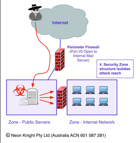
Previously in the castle analogy we saw the use of wards and chambers. At a network level, the purpose of a security zone is to provide network level compartmentalisation, also known as Segmentation. One of the most critical foundation concepts within modern network security design is the use of security zones to segregate various areas of the network from each other, and to control the communication between the various zones. Different devices within the network will have differing security needs, for example, database servers holding credit card information will need to be located in a highly secure zone with tight access restrictions. Whereas the mail relay and external DNS servers will require placement with reasonably open access to the Internet.
Should a device within a security zone become successfully compromised, then the zone concept provides the ability to limit or contain the progression of the attack.
To achieve these goals, a policy enforcement function is required between zones. By this we mean the ability to control traffic between zones in line with the overall design objectives. A policy enforcement function can be deployed using a number of devices. At the simplest level it may be an Access Control List (ACL) on a router or switch, an approach which was used for many years. These days ACLs are often processed in hardware and are cheap and fast. However, in most cases it will be Firewall, or at the Internet perimeter, possibly a Network Proxy. While these devices provide differing capabilities, at the simplest level they control traffic between zones.
Two classic zoned security architectures are illustrated below. The first being a classic Internet, DMZ, internal network Internet perimeter design. The second being a classic three-tier design often used for hosting a dynamic web application.
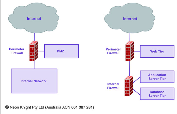
As noted above, the basic concept is around thwarting network based attacks. For example, a mail server needs to communicate using SMTP to any other mail server on the Internet. Should that device get compromised and become externally owned, then we don’t want that server to have unrestricted access to other devices in the network, allowing the attack to easily spread. With the mail server located in the DMZ, then mail-clients on the inside network can establish a connections from the internal zone, to the mail server to retrieve mail. Through directional connection control, the mail server can not establish connection into the Internal network. In the event of a mail server compromise, then it fundamentally can’t access Internal devices.
While security policy enforcement between zones has typically been the primary objective, the devices implementing this function, or additional devices, can potentially provide a strong visibility element through capabilities such as logging, application identification, rule match statistics, NetFlow, IDS, Deep Packet Inspection, etc.
The network security device connecting zones can also be thought of as a choke point. In other words, a deterministic path through which network traffic between two zones flows. It is here that other network level, policy enforcement functions can be performed. The most common of these is Intrusion Prevention Services (IPS), others include devices such as Web Content Filters, and AV scan engines, etc.
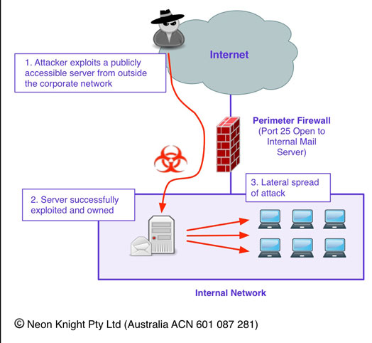
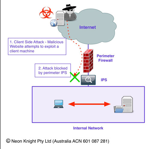
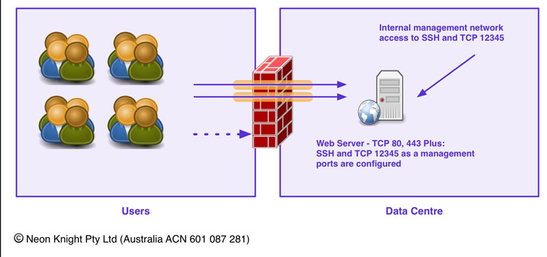
Where a Firewall alone doesn’t protect you..
Its important to understand where a Firewall provides effective protection and where it doesn’t. Figure 6 provides an example of a very common attack scenario today. An inside user has their machine compromised through a client side attack. In this example, they visited a malicious website which took advantage of a vulnerability in their web browser. Alternatively, it could have just as easily been a Phishing attack, or the compromise could have occurred when the machine was out of the office. In any case, the net result is the same. A compromised machine is on the inside of the network, under the control of an external party.
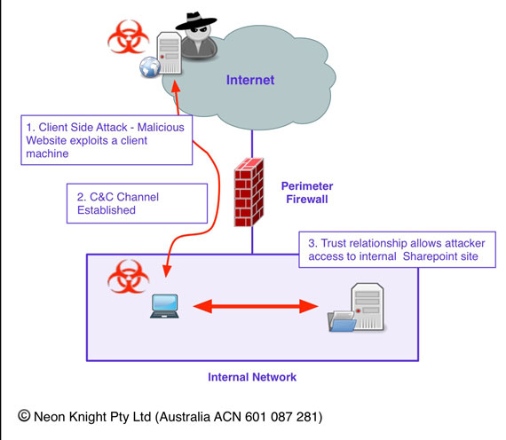
The user has valid credentials for access to a corporate Sharepoint site where confidential data is stored. The attacker has control of the machine and as a result of that trust relationship, has access to that data which can be easily exfiltrated out of the organization.

To prevent this attack from being successful, it is necessary to utilise an IPS to (hopefully) detect the Command and Control (C&C) Channel of the attack. Most quality IPSs will provide this capability for known C&C signatures. While in this example I have added the IPS later in the example to detect and block the C&C activity, an IPS would have prevented the client side attack from succeeding in the first place. However, it would not have prevented that attack from succeeding if the machine was compromised when outside the office, and then rejoining the internal network.
Even if an internal Firewall was located between the user and Sharepoint server (typically located in a Data Centre), it would not have helped in this case as the traffic from the user to the Sharepoint server would likely be entirely legitimate.
The key point from this example, is understanding the security function (or control) which each device provides, and conversely what functions it does not provide.
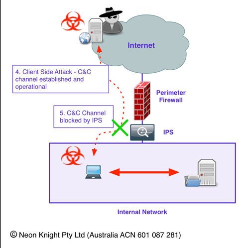
For completeness, Figure 8 shows the initial attack being blocked by the perimeter IPS.
Dual Homed Servers as a Security Architecture… A bad idea
A this point it is worth discussing the use dual homed (or multi-homed) servers or hosts as a secure architecture. I mention that as I have personally seen architectures designed like this with the architects thinking it a secure approach- it isn’t!
While there are security controls which can be deployed on a per-interface basis, like host based firewalls, or IP-Tables, etc, an interface can not be secured independent of the host. If host is compromised, the attacker will have full control of that device including every interface. This allows them to progress an attack through any convenient interface to the next target.
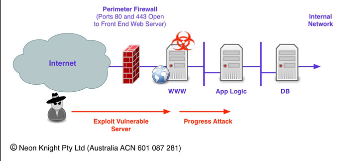
Figure 9 provides an illustration of this concept. In this case, an Internet facing Web Server is hosting a dynamic web site. While a firewall is reducing the attack surface of the web server, the firewall needs to allow traffic through ports 80, and 443 for the web site to function. Should that web server be, or become vulnerable, then an attacker can compromise that web server and then easily progress the attack to the other connected servers, in this case the Application Logic Server through the right side interface.
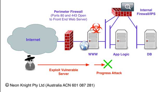
Figure 10 illustrates a far better approach of using an internal Firewall and IPS to prevent the attack from progressing.
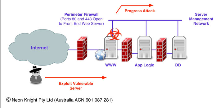
Finally, if management interfaces are utilised on servers, connected to a management network, then be aware that these networks can be an easy backdoor to bypass security controls.
Yes, I have seen this done, often by a systems administration group without the knowledge of the security team. Be mindful this is very easy to do in a virtualized environment since VNICs and switched networks can be easily created with a few mouse clicks.
For completeness, Private VLANS are a feature of many higher end network switches which can be used within management networks. Private VLANs allow individual ports on a Layer-2 VLAN to be isolated from each other, while still being able to communicate with a promiscuous port. Virtualised versions of the same capability are also available.
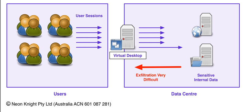
Virtual Desktop Infrastructure
The use of Virtual Desktop Infrastructure (VDI) is becoming an increasingly common security architecture practice. Two notable applications include BYOD environments, or often the principal is also used for Jump hosts in management networks. VDI provides the capability to isolate critical data from the users who are accessing that data or the systems on which it resides. Previously Figure 6 illustrated an example of compromised user with a trust relationship to SharePoint server. A VDI architecture makes it a much harder proposition to exfiltrate data from the organisation.
Obviously such an approach comes at a cost in terms of compute and storage resources, licensing and operational costs. On this basis, it is normally reserved for the more highly secure environments. However, given the sophistication of attacks and the value of data in many environments, VDI is an approach which should be considered as a design option if the protection of data is a key requirement.
Zoned Security Architecture Design
In todays world, highly complex interactions often occur between various elements within an information system, or application architecture. Some simplified examples were illustrated previously in Figure 5, but typical large scale environments will normally be significantly more complex. The goal of this section is to explain the fundamental concepts of traditional ‘Zoned Security Architecture Design’. To do this, I will make the assumption that we are dealing with a greenfield environment. The topic of re-designing an existing, potentially complex environment may involve additional considerations which may be discussed in a later White Paper.
The most important outcome from a ‘Zoned Security Architecture Design’ is an optimal placement of systems into the most suitable security zones. With a system located within a suitable zone, any traffic flows to other security zones, should be explicitly permitted through firewall security policy (i.e. rules). This is also known as Inter-Zone traffic. Traffic flows within the zone are generally allowed without restriction. This is also known as Intra-Zone traffic. Although there are approaches to performing security policy within a zone as well, I won’t discuss that here as its getting beyond the intent of this section.
Two primary design considerations should be understood up front;
- The System function and role, its sensitivity, and threat susceptibility.
- The System-to-System, or Device-to-Device communication requirements or transaction flows. This point can not be emphasised enough.
The criteria for locating systems into a zone can include;
- High value targets or systems containing sensitive or valuable information.
- Systems which are part of the same tier of an N-Tier application architecture.
- Systems with similar security requirements.
- Like role or function.
- Systems requiring significant or complex interactions within the zone (Intra-zone communication).
- Systems with common or similar communication requirements outside of the zone (Inter-zone communication).
- Regulatory requirements such as PCI DSS.
There are no hard and fast rules dictating the size of security zones. A highly secure zone, such as a cardholder database, may be very small, possibly only containing a few servers. An Internet Perimeter DMZ, may similarly be fairly small, only containing the necessary systems. Whereas the zones which contain the bulk of the user systems may potentially be fairly large. The key point is to determine both the security affinity of the various systems and communication requirements between those systems. This is both somewhat an art as well as a science.
In practice, the communication requirements of most systems are usually substantially more than the usually known system to system communications within an application stack. Most systems will require communication with common services such as DNS, Network Time Protocol (NTP), AV updates, system management and monitoring protocols. All this needs to be considered when designing a zone structure.
The overarching goal of this design process is to achieve the highest possible security posture, while allowing a functional and manageable overall system. Like any engineering process, it is about balance and trade offs. While no system is 100% secure, the design can certainly create a very restrictive environment for systems which require the highest levels of protection. Likewise, for systems which do not have a the same protection requirement, then a more relaxed posture is appropriate, for example the typical inside network where the user systems (i.e. PC/Mac populations) reside. This does not mean ignoring proper security design or fundamental security controls, but implementing an appropriately functional environment suitable for day-to-day operations. For user environments, it can be counter productive to unnecessarily implement an overly restrictive environment. This sort of situation can lead to users implementing highly risky approaches to getting their jobs done.
The zone design needs to be performed in a manner which allows the security policy between zones to be simplified as much as possible. A poorly designed zone structure leads to the need for highly complex rule sets, increased complexity, increased management effort and the overall operational cost. So a good understanding of the transaction flows and traffic patterns is very important when doing security zone design.
Understanding the Traffic
When planning a zoned security architecture, in addition to the communication requirements between system elements, it is also necessary to understand:
The direction of the communication flow, or in other words, the element that initiates the conversation or connection. Firewalls normally provide directional connection control, meaning that once a connection is initiated, return traffic is allowed to flow back to the initiator. In some case the direction may not be known, but it is highly desirable to define the direction ahead of rule creation. As far as possible it is desirable to have connections between zones initiated from the more secure or trusted zone, to the less secure or trusted zone. However in practice application developers rarely develop there application stacks with optimal security in mind.
The application level Protocol. While firewall rules can be created based on Protocol and Port (i.e. TCP/UDP, Port No), firewalls are capable of inspecting a number of protocols to a greater degree to ensure RFC compliance. Knowledge of the protocol, such as HTTP, SMTP, ESMTP, DNS, etc allows a deeper level of inspection to occur, which is highly desirable, otherwise the firewall just acts largely as an Access Control List. (ACL).
Zone based Firewall Policy
All the major firewall vendors (Cisco, Palo Alto Networks, Intel Security formerly McAfee formerly Stonesoft, Juniper, Fortinet) utilise a zone based concept in their products. The notable exception is Checkpoint who utilise an interface in a similar manner.
Zone based firewall policy is a form of abstraction. Abstraction is a method of managing complexity.
By abstracting the concept of a zone from an interface, it becomes possible to group multiple interfaces as a single zone and then apply security policy in a single instance. Where many interfaces are involved, this approach potentially allows a reduction in the overall rule base size. Decoupling the Security Policy from the network interfaces also allows the network layer to perform routing and forwarding functions independently of each other. For example, functions like Equal Cost Multi-Path (ECMP), Policy Based Routing/Forwarding (PBR/PBF), tunnels, etc.
The approach of organising security policy on a Zone-to-Zone basis, potentially allows the abstracted construction of firewall rules and security policy. When assembling security policy, formulating it on a Zone-to-Zone basis allows for a logical grouping and potentially better readability of the policy sets. Experience has shown that a well utilised zone approach to policy construction can produce simplified and more manageable security policy.
Modular and Functional Design
The concept of modular design allows a network security architecture to be based on modules performing specific, repeatable functions. Modular design is a key principal which allows a network to scale. Each module can be built around and specific function and upgrade and growth paths can be based on modules, not individual elements.
Functional design is based on the principal of each device in the design having a specific set of functions. Specific devices can be selected based on their strengths. In the past, functional design would largely work on the premise that “one box could not do everything – no matter how hard you tried”.
While in a lot of cases in security design this premise was true, ‘Next Generation’ devices are providing multiple capabilities within a single device (Application Firewall, IPS, AV Scanning, URL Filtering, Data Leakage Protection, File Blocking, etc). In contrast to individual function specific devices, Next Generation devices, such as Next Generation Firewalls provide a ‘Tight Coupling’ between the individual functions within the one device. This can be a very valuable capability in a security design.
An Example Enterprise Zoned Security Architecture
Figure 13 provides an illustration of an example modular network security architecture, This approach can be used or adapted for small to medium size networks. The goal is not cover every possible aspect of network security architecture, as that is a far larger discussion, but to define a basic fundamental structure. Large corporate networks will certainly be more involved, but these basic modules should be common. With that said there are certainly some very large environments (tens of thousands of users) built of this fundamental structure. On the flip side, smaller organisations have some of the greatest challenges. They have to do more with smaller budgets and less staff with a more generalised skill set. So having the ability to employ the same principals, but on a smaller scale, is also important to understand.
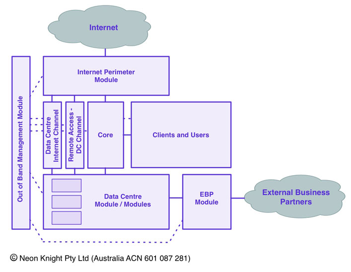
Internet Perimeter Module
The purpose of the Internet Perimeter module is to provide the demarcation point between the Internet and the Internal network. At a most basic level it typically permits traffic to flow from a more secure internal network, to the Internet, but not from the Internet into the internal network. While it is represented in Figure 12 as a discrete block, the services are normally physically collocated in the Data Centre.
The requirements of an Internet Perimeter Module can vary widely from organisation to organisation. Typically this module will utilise one or more Firewalls, Next Generation Firewalls, Network Proxies, IPS, URL Filters, AV scanners, etc to achieve the desired goals.
The Internet Perimeter Module should also be concerned with outbound connection control and the traffic which is exiting the enterprise. This is now one of the more significant goals when recent attacks have exfiltrated valuable or sensitive data from an organization. Certainly Data Leakage Prevention solutions provide sophisticated solutions to this issue, and that a significant topic in itself. However, at a more fundamental level, controlling application usage through the Internet perimeter can provide a significant improvement to the overall security posture.
Typically, a perimeter DMZ network will exist within this module, where servers like a recursive DNS server, mail relays and other servers supporting Internet services would reside. With respect to DNS, the Internet Perimeter Module will normally include the recursive DNS infrastructure to resolve addresses to support outbound connections to the Internet. DNS architecture is a topic in itself and will be covered in a subsequent White Paper.
The Internet Perimeter Module will normally need to service a number of discrete internal security zones. This includes the general user population and usually multiple zones within the Data Centre. The requirements for Internet access from the Data Centre will be very different to those of the general user population, in particular the applications crossing the Internet perimeter. As such, a dedicated isolated communication channel or channels, should be used for the various data centre applications and services to access the Internet when required.
Users and Clients
The User and Client Zone is where the end user systems and devices, such as desktops, Laptops, and IP Telephones and other office systems will be connected. Today, these systems are normally not collocated with the Data Centre and usually connected through a core network or WAN link.
Within a User Zone, IP Telephone is usually run on dedicated VLANs, separate to the Users Laptops and Desktop systems.
Although this example only illustrates one zone, in a large network, usually multiple sites will exist. Each of these can be broken into multiple zones if required. While compartmentalizing the User Network into multiple security zones is a prudent practice, the use of Peer-to-Peer applications, such as Soft-Phone instances is a design consideration.
Printers and Multi-Function Devices
Printers and Multi-Function Devices often reside in the same security zone as the user population. These devices are notorious for being unpatched and having known, easily exploited vulnerabilities. Although not illustrated, it recommended they be contained within their own security zone.
Core
The purpose of the core network module is essentially to provide high speed transport, with Quality of Service (QOS), between the various modules within the network. This may include Wide Area Network communication services, which are usually required to facilitate communication between office premisses and the Data Centre. In a larger organisation, the core network may be more than an single domain, IP routed network. It may provide IP VPN services, possibly based on MPLS, to provide separated transport services for different domains within the organisation.
Data Centre
Today most organisation will locate their core IT assets within a Data Centre or colocation facility. In any case, it needs to be viewed as a discrete module from an architecture perspective. Whether it is a small or large requirement, physical or virtualised, the primary goal from a security design perspective is to implement a layer of policy enforcement in front of the systems which reside within this module. In most cases today, that policy enforcement device will be a firewall, firewall and IPS combination, or a Next Generation Firewall, or a virtualised form factor of one of these. However, if budgets are constrained, then a set of stateless ACLs on a layer 2 or 3 switch can provide an effective level of attack surface minimisation. The key point is that there should be a layer of policy enforcement between the user population and the servers hosting applications in the Data Centre.
If we move beyond the fundamental goal, the Data Centre module may be a highly complex security architecture, or set of security architectures in itself. For most larger organisations this will include databases, and n-tiered application stacks, with firewall and IPS separation. Today, most this will be deployed on virtualised infrastructure.
The topic of Data Centre security design is one that will easily fill a large White Paper or book. So the intricacies of the topic is something that can be explored in more depth at a later point.
External Business Partners
Today, just about every organisation has external business partner relationships. In the case of the financial sector, many of these will involve back end systems communicating with the back end systems of another financial organisation. For other sectors like retail, it may be links to suppliers. In any case, the purpose of this module is to implement a set of policy enforcement controls which strictly limit access to the internal resources and prevent attacks from the partner organisation in the event that organisation was compromised. Like the perimeter of the data centre, it is a trust boundary and will usually be implemented on a firewall and or an IPS.
Out of Band Management Network
An Out of Band Management Network (OOB) should today be an essential part of any network infrastructure, irrespective of size. In Band access to network infrastructure in this day and age should no longer be used. While there is a cost to establishing an OOB network, it is not great. Today the major firewall vendors all produce highly capable low end firewalls with integrated IPS for a few thousand dollars (i.e. Cisco ASA5506 or a Palo Alto Networks PA-200). These devices coupled with a quality L2 switch and private VLANs, can implement a very functional and secure OOB management network.
Remote Access
VPN based Remote Access (IPsec or SSL) will typically be supported within the Internet Perimeter Module. A dedicated channel should support the connectivity to the services within the Data Centre to avoid this traffic unnecessarily traversing the User Module.
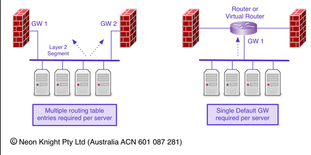
Routing with Multiple Gateways
Although a little outside the topic of Network Security Design, it is worth briefly covering the topic of server nested between two or possible more firewalls. The issue that arises from this design approach, as illustrated on the left diagram of Figure 14, is the fact that multiple routing table and gateway entries are required in each server. I have seen situation where security people are reluctant to deploy this sort of architecture due to the routing complexity required on multiple servers.
The issue however can be easily addressed with the use of a virtual router or VRF between the two firewalls. The diagram on the right of Figure 14 illustrates the approach of a single default gateway on each server, and the more complex routing handled through either static or dynamic routing or the virtual router or VRF.
Firewall Rules Definition and Creation Process
Previously we have seen a design and implementation process which included the definition of security zones and the placement of the individual system elements into appropriate security zones. This design has a direct bearing on the firewall rules and the overall complexity of the rule sets across the various firewalls or firewall contexts within the system. The importance of a well thought out structure can not be over emphasised.
As noted previously, in addition to the location of the system elements, it is also necessary to understand
Previously we also discussed system-to-system communication requirements which can generally be grouped into four categories:
- Pre-defined communication such a specifically known device-to-device flows, or transaction flow requirements, say within an application stack.
- Additional Services: Most systems will typically need to make use of a number of common services such as DNS, NTP, Syslog Log Receivers, Load Balancers, Anti-Virus servers, as well as other services.
- Access for system administration and maintenance. For example, SSH, RDP, etc.
- Unknown requirements: The stuff you haven’t thought of, or the stuff other people don’t tell you.
It is also necessary to understand the direction of the communication flow and the protocol.
The IP addresses of individual elements are required and are normally defined through a separate IP address allocation scheme. Based on that information, the creation of firewall Security policy (or rules) can occur.
Named Objects
Individual systems, or system groups, will usually be created as Named Objects and Named Object Groups. These named objects can then be used within the Security Policy (firewall rules). The use of Named Objects abstracts the element name from its IP address. This allows for both a more meaningful name, avoiding the need to know the actual IPv4 or IPv6 address, as well as the ability to easily change an address without needing to alter the actual firewall rules.
A Named Object can be;
- A single address
- A group addresses requiring a common policy.
- A Port representing an application
- A Group of ports required for an application
Named Objects can then be used within Security Policy, and hopefully make that policy more readable as a result.
Firewall ACL and rule implementation
With a set of Named Objects in place, or at least determined, then the actual Firewall Security Policy (or Rules) can be constructed. Traditionally, firewall security policy has been based on the ‘Five Tuple’ of;
- Source IP Address
- Destination IP Address
- IP Protocol Type – TCP, UDP, ICMP, etc
- Source Port
- Destination Port
Next Generation devices can offer additional policy elements including;
- Application, at a highly granular level
- User Identity – often determined from Active Directory or other identity stores
- URL Categories
- Security Tags
- Geolocation
- File policies
As there is plenty of good documentation on this process in vendor documentation, I won’t spend time trying to repeat that information here. The key point is that if the fundamentals have been though out ahead of time, then the actual construction of the Security Policy should just be a process.
As noted above, Next-Generation devices offer additional security policy elements. In particular, a far more granular level of application control and the ability to utilise user identity information directly in the policy. In many cases, these additional policy elements can allow the creation of simpler, more concise security policy when used appropriately. Additionally, the fact that additional policy elements can be utilised within a single rule, allows some every effective policy to be easily created. For example;
- Block all traffic to risky counties via geo location.
- Prevent file downloads from high risk URL categories
- Prevent users posting to Facebook or other social media sites from the corporate network.
- Allow only the marketing department to post to Twitter
- Allow outbound file transfers by only user groups with a business need to perform this function.
- Allow the use of the corporate standard for browser based file sharing, but no others.
Like with any enhanced capability, it must be used in a well thought out manner to avoid creating an unstructured, unmanageable mess. Again, I emphasise my point on the need for prior planning and a structured approach.
Security Policy Granularity
Firewall rules can be very loose, or very tight. By very loose, we mean allowing multiple flows or communication streams through the one rule. By very tight, we mean defining the rule such that it only allows a very specific flow or communication stream through the rule.
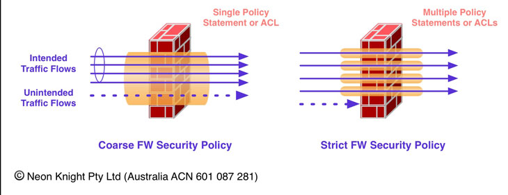
There are pro’s and con’s to both approaches. It is essentially a matter of making a design decision most appropriate to the individual deployment scenario and risk profile. Less specific rules provide a less restrictive posture, with a generally significantly lower rule count and overall rule base complexity. On the other hand, more specific and tighter rule sets generally provide higher security posture, but with an increased level of complexity and increased rule maintenance effort.
Firewall Rule Complexity
It is worth understanding the relationship between Rule Count and overall complexity and maintainability to aid in making appropriate decisions in relation to rule definition policy.
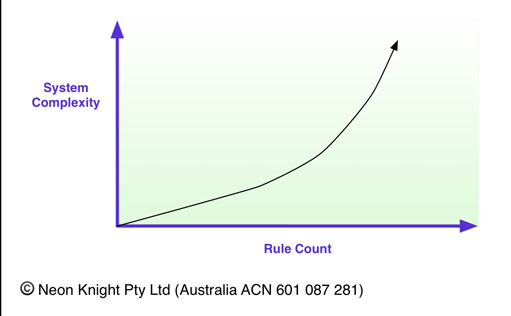
While it’s hard to quantify exactly, and a number of factors are involved such as the granularity the individual rules, Figure 16 loosely illustrates the relationship between rule count and overall complexity. Generally speaking, as the number of rules increases, the complexity can start to quickly accelerate.
I have seen many environments which were initially well intentioned, but over time became unmaintainable. When an environment gets to this point it becomes counter to the original goal. In addition, experience has shown that firewall rule base complexity typically increase with system age. In practice, unless rule bases and the associated documentation are diligently maintained, old, unused rules are often left in place and not removed when no longer required.
Wrap Up and What’s Next..
The primary goal of this White Paper was to explain the fundamentals of Network Security design. I actually wrote this White Paper after I commenced the writing of a White Paper on “The new considerations in Network Security Architectures – 2015 and beyond”. I quickly realised that it was firstly necessary to cover the fundamentals, before I could discuss the new considerations.
From here, I will move onto a second White Paper, and my initial goal of discussing the new considerations in Network Security Architecture.
©Copyright 2015, Neon Knight (Australia) Pty Ltd
ACN: 601 087 281